
On the other hand, the following conceptual error can easily be made using flow conduits when dealing with the following system:
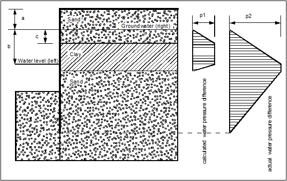
p1 = γw · c
p2 = γw · b
The permeabilities of the clay and sand layers are 1·10-8 m/s and 1·10-4 m/s, respectively. Although the program conforms completely to potential theory, the calculated difference in water pressure, p1 [kN/m²], does not correspond to the distribution of pressure that would be expected. Based on what has already been described, the application assumes a current of water in a flow conduit parallel to the wall from the water level on the right to the water level on the left of the wall. At the top right-hand end of the flow conduit the water level corresponds to the right-hand water level, while at the top left-hand end of the flow conduit it corresponds to the left-hand water level. The reduction in water pressure between these two points is now determined according to potential theory. The resulting difference in water pressure between the left and right sides corresponds to the distribution p1 shown in the figure above, and according to the applied method is perfectly correct.
However, if the groundwater level below the layer of undisturbed clay is the same as that above it, this approach will produce an erroneous value for the water pressure distribution. In the above example, the water pressure below the layer of clay will be determined almost entirely by the water pressure in the excavation. If the water pressure below the layer of clay is to correspond with that above it, using flow conduits, a potential of
h = a
must be defined on the right side, below the layer, to achieve the desired distribution of water pressure differentials, p2, as shown in the figure above. Although the program conducts plausibility checks, there are nevertheless situations in which an analysis without additional definition of a potential below the clay layer is useful. Whether or not the computed difference in water pressure is what you had in mind can be easily checked by selecting the "Differential water pressure" command button in the dialog box that appears when you click "Graphics output preferences" in the "System" menu. Then the program graphically displays the difference in water pressure between the left and right sides of the retaining wall.