
The system is available as the DXF file "Manual.dxf". Input of the coarse system structure can be considerably simplified by importing the DXF file into the graphics using the "Mini-CAD" module and then clicking the principal points with the mouse.
To do this, point at "Graphics preferences/Mini-CAD toolbar". A popup window with icons appears at the bottom right. Click the "DXF import" tool ![]()
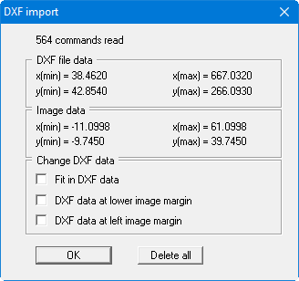
Refresh the system visualisation using the [F9] function key. As you can see from the dimensions in the graphics, the coordinates of the scanned graphics do not match the axis coordinates. To correct this, proceed as follows:
A dimension line is shown at the top left; it should be 15.0 m long. Double-click on this line with the left mouse button to open the editor box.
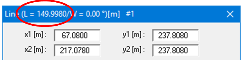
The actual length of the line is given at the top edge of the dialog box (L = 149.9980). This gives a reduction factor f (target/actual) in the x direction of:
f = 15.0/149.9980 = 0.1
To determine the reduction factor in the y direction, click the vertical dimension line, which is specified with a length of 6.0 m. In the line's editor box a true length of 60.0030 m is shown.
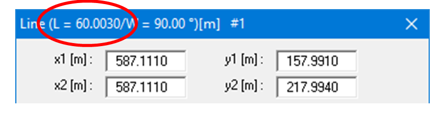
This gives a reduction factor in the y direction of 0.1.
In order to correspondingly adapt the drawing, select the "Modify objects" icon from the Mini-CAD toolbar ![]()
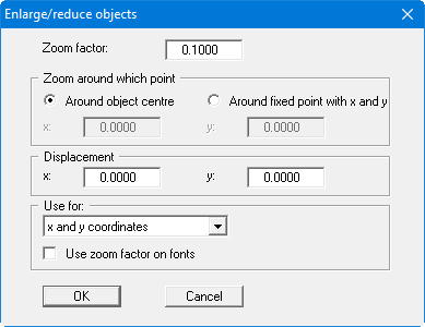
After exiting the dialog box by pressing "OK" your graphics will be shown substantially smaller. Press the [F9] function key again to refresh the coordinate system and scale.
Double-clicking the dimension lines shows you that the scale of the graphics fits, only the elevations are not yet correct. Therefore, now double-click the bottom of the basin, which should be at 15.0 m AD, with the left mouse button.
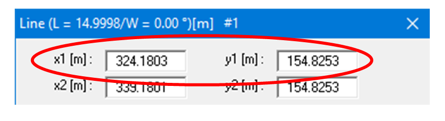
Here, the x1 and y1 data are decisive. If the left margin needs to be at an x value of 0.0 m, you can displace the graphic in the x direction by -324.1803. For displacement in the y direction, the following value is returned:
![]()
To displace the drawing correspondingly, click again on the Mini-CAD "Modify objects" icon ![]()

After exiting the dialog box by pressing "OK", press the [F9] function key again. Your graphics are now visualised with the correct coordinates and scale. You can now very easily click the system's governing points with the mouse.