
Go to the "Mesh/Define nodes" menu item and activate the "Lock-on to Mini-CAD lines" check box in the dialog box.
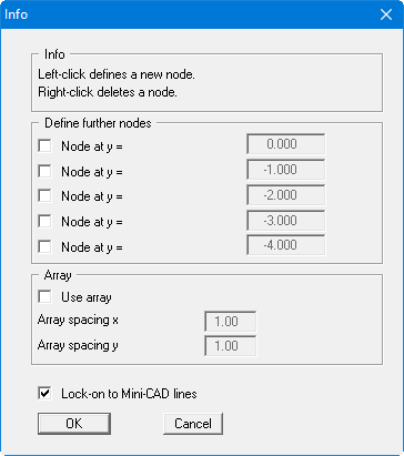
After exiting the box by clicking "OK", the mouse cursor appears as a rectangle. If the end points of Mini-CAD lines are within this rectangle, the program will lock-on to these end points. You don't need to exactly hit the end points.
Now click all principal points in the system (including the intersection of water table and slope), in any order. Take care to ensure that the mouse cursor rectangle surrounds the necessary Mini-CAD line ends. In all, you must click on 15 points.
Finally, donate a further point at x = 25 and y = 5 (centre of bottom system edge). This auxiliary point only serves to give a nicer mesh for the following mesh creation. As none of the DXF lines end here, a node at this point will not exactly match the coordinates given above. In order to position this point exactly select the menu item "Mesh/Edit" and double-click on the nodes. Then enter the coordinates.
Now go to the menu item "Mesh/Automatic". The program connects the 16 nodes to a triangular mesh. The program creates a mesh which surrounds all nodes. For this reason, 2 to 3 superfluous elements are created on the water side and on the air side. To delete these, select the menu item "Mesh/Delete" and trace around the centroids of the superfluous elements with the rectangle.
The three different soils still need to be defined. All triangles were automatically assigned soil number "1" during mesh generation. This soil number will represent sand. Now go to the "Boundary/(soils) In section" menu item and trace with the rectangle around the areas to be defined as "Clay" (water-side seal) and assign the soil number "2". Do the same for the drainage and assign the soil number "3".