
In order to set boundary conditions go to the menu item "Boundary/(Potentials) In section" and circumscribe the nine FEM nodes at the left side of the system.
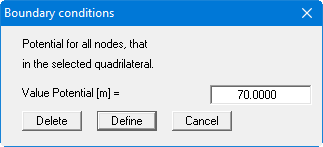
Enter a potential of 70 m AD and accept it for the selected nodes by clicking the "Define" button. Trace around the nine FEM nodes on the right of the system and enter a potential of 69 m AD.
Point at the "Boundary/Individual potentials" menu item and click the "Graphical" button in the box. Now click the well, that is node 5 in the centre of the system, and enter a potential of 65 m AD.
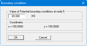
If you have problems actually hitting the node, enlarge the screen view by tracing the inner region with the left mouse button and the [Ctrl] key pressed. The [Esc] key resets the screen to an overall view.
Note on boundary conditions:
The case of an impermeable boundary is automatically taken into consideration by the finite-element method. Valid is, that all system boundaries or partial boundaries, which do not posses source or potential boundary conditions, are automatically impermeable. In finite-element theory, this type of boundary condition is also known as a natural boundary condition.