
Following, a concrete example of calculation of a horizontal-plane system will be shown. A system with the following dimensions is to be investigated:
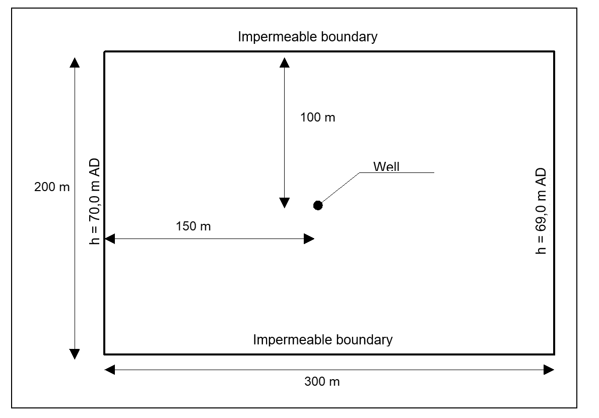
The system is depicted in the figure in plan. A section of the groundwater system of 200 · 300 m is to be considered. It is known from groundwater level measurements that without the influence of the well a parallel groundwater flow, from left to right, is present. The water level at the left system edge is 70 m AD and at the right system edge 69 m AD.
The subsurface consists of sand (k = 2·10-4 m/s), which is covered by a cohesive, slightly permeable valley loam. The top of the sand horizon is at approx. 68 m AD, so slightly confined conditions are met. The base of the sand horizon falls roughly linearly from 59 m AD at the left edge, to 51 m AD at the right edge.
The influence of the well, for a drawdown to 65 m AD, is to be investigated. Apart from the discharge, the areas which are no longer confined during well operations are to be investigated.