
A colour-filled contour diagram of the potentials will be generated for the selected layer surface. If you currently find yourself in a sectional representation, select the menu item "Mesh(x/y)/Mesh" to return to the plan view.
Select the menu item "Evaluation/Coloured" and then "Potentials" in the subsequent option box. A dialog box then opens, in which you can have the program determine the minimum and maximum contour value by pressing the "Determine extreme values …" button.
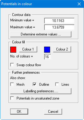
In order to achieve clear grading in 25 cm steps in the colour bar, enter "10" as the minimum contour line value and as maximum "15". Set the number of colours to "21" and confirm the changes using "OK".
You will now see a contour plan of the current node plane. Move through the planes using the two tools ![]()
![]()
If you prefer a simple line representation instead of coloured graphics, go to the "Evaluation/Normal contours" menu item.
The term "horizontal" used in the heading for this section is incorrect inasmuch as the node planes need not necessarily be horizontal.