
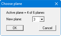
First, using the ![]()
Now define a section as shown in the figure below using the menu item "Evaluation/Values in section" or load the section provided in the "Example.fes" file by pressing the "Load section" button.
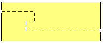
Press the [Return] key. The section will be displayed. Now select the "3D/Potential external model" menu item and confirm the default projection preferences. The following dialog box appears:
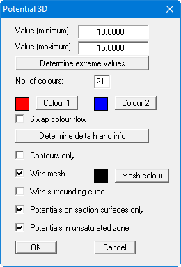
Confirm your entries with "OK". You will see the cut-away system as a 3D representation (see also "Ex. step 10 Potential external model.f3d" file). Move through the planes using the ![]()
![]()
![]()
If you select the "External model" menu item instead of the "Potential external model" you will see the soil colours (see "Ex. step 11 External model.f3d" file)or a shaded system of your 3D mesh instead of the potentials.