
During the previous mesh generation, all new elements were assigned the soil number "1". In order to allow the sealing layer to later be assigned a different permeability, these elements must be assigned the soil number "2". Go to "Boundary/(Soils) In section".
At the top right a schematic of the current plane and layer are shown. Use the ![]()
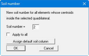
Assign the soil number "2" and leave the dialog box with "OK". The "Apply to all" check box should not be activated under any circumstances, otherwise all layers in the defined region will be assigned the soil number "2". If you have captured too many triangles, you can make corrections via "Boundary/Individual soils" or simply draw a new polygon around the incorrect area.
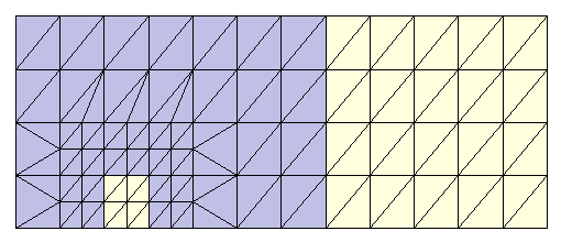
The weak spot is given the same permeability as the subsurface of the embankment (soil number "1"). So, travel with the mouse around the weak spot and assign it the soil number "1". The following visualisation results (see file "Ex. step 04 Weak spot.f3d"):
Check your input using "z/Define section" to define a section along the lower system boundary (as seen in plan). Press [Return]. The FEM mesh is represented in section. If necessary, activate the check boxes "Coloured" and "With soil no." in the "Mesh(x/y)/Preferences" menu item. Now go to "z/Outline". The sealing layer and the weak spot should now be visible. Do the same for the upper system boundary. Here, only the sealing layer should be visible.