
If you still find yourself in a sectional representation, go to "Mesh(x/y)/Mesh" before defining boundary conditions and return to the plan view.
To define boundary conditions go to "Boundary/(Potentials) In section" and travel around the FEM nodes on the left of the system, including the row of nodes making up the left edge of the embankment top. Check beforehand that you are still in the uppermost plane 3 and if not use the ![]()
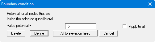
Make sure you deactivate the "Apply to all" check box to ensure that only the nodes on the uppermost plane are allocated a potential of 15 m AD (= water level on the water side), and not the nodes on the planes below this.
Now travel round the nodes on the right of the system, including the row of nodes making up the right edge of the embankment toe and allocate a potential of 10 m AD (= surface of embankment hinterland).
Check your input using "z/Define section" to define a section along the lower system boundary (as seen in plan). Press [Return]. The FEM mesh is represented in section.
Go to "Boundary/Individual potentials" or "Boundary/(Potentials) In Section" menu items. The potentials are represented in the selected section (see also "Ex. step 05 Potentials.f3d" file). In this section, too, you can edit the potential boundary conditions. However, this should not be necessary if everything was entered correctly.
Remark on boundary conditions:
The case of an impermeable boundary is considered automatically by the finite element method. All system boundaries, which do not possess source or potential boundary conditions, are automatically impermeable. In finite element theory, this type of boundary condition is also known as a natural boundary condition. The selected boundary conditions on the water-side assume that the embankment is not percolated from below by the river water, which may intersect the cover layer. If you want to model this, you will have to also create a continuous weak spot on the river-side.