
The FEM mesh will be displayed at the nodes, together with the calculated discharge. Discharges other than zero are present at the nodes at which you have defined a water level boundary condition or a source boundary condition. At all other nodes the discharge equals zero (continuity condition). Using the dialog box you can specify the type of presentation.
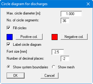
After leaving the box using "OK" the discharges are displayed as variable sized circles. Positive and negative discharges can be displayed in different colours in filled circles.
By specifying a appropriate areas of the screen, the sum of the discharges in these areas can be calculated by the program. By clicking any four points anti-clockwise the discharge in the enclosing polygon is determined for the selected plane and for all other planes and displayed in a message box.
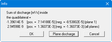
You can then calculate the plane discharge for the selected area. The plane discharge is the discharge flowing through the triangles contained within the quadrilateral of the current plane. It is calculated from the node discharges of the triangular prisms located below the plane. Under certain circumstances, the boundary nodes may include a component belonging to a neighbouring prism not included within the quadrilateral, leading to slight inaccuracy.