
Before you import DXF data, you should move to a new layer to be able to edit the imported objects without having to pay attention to existing objects.
After clicking the "DXF file" button the following dialog box opens:
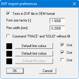
If you encounter problems when importing fonts from the DXF file, e.g. special characters are not correctly represented, you may be able to achieve better results by deactivating the "Texts in DXF file in OEM format" check box or by applying a font size factor. If colour fill does not need to be imported, activate the "Command TRACE" and "SOLID without fill" check boxes. If coloured lines or texts are to be imported from the DXF file, deactivate the "Use" check box for the appropriate standards.
Select the required DXF file from the file selector box after clicking "OK". The program interprets the DXF commands and converts them to GGU-CAD objects. The following dialog box opens:
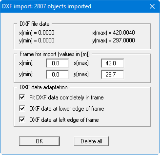
In the upper group box information on the dimensions of the DXF file and the image data for your current project can be seen. The image data are given in the "Frame for import" group box. However, you can also enter a region of your drawing where the DXF file shall be displayed. If you click the "Delete all" button in the dialog box above, the data in the current DXF file will not be imported.
If you have already correctly defined your drawing scale and the DXF data have been transferred with the correct coordinates, you should deactivate all check boxes in the "DXF data adaption" group box.
However it is useful in many cases to let the lower three check boxes in the dialog box be activated (default setting). The program then ensures that the DXF file fills the screen. In order to adjust the scale and the coordinates of the DXF data to that of your drawing project proceed as follows:
-
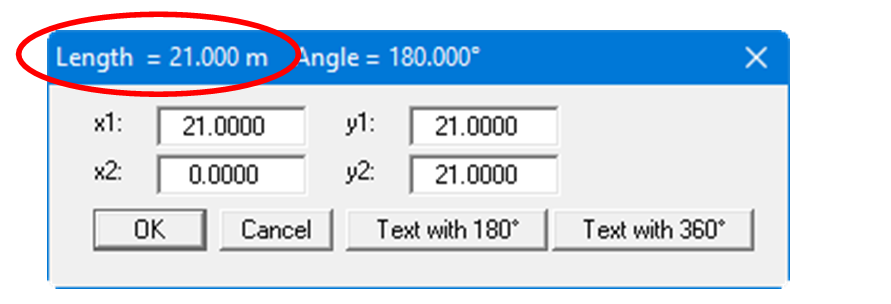
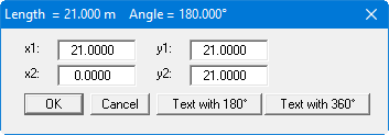
Find a horizontal and a vertical line in the imported DXF data of known lengths. You can also draw an auxiliary line between two points of known spacing. After going to the menu item "Draw/Edit object" or pressing [F3] click the lines and then the "Coordinates" button in the dialog box. The actual length of the clicked line is given on the blue bar of the dialog box.
-
If the required length is divided by the actual length the result is the zoom factor for the size correction. Because different heights and widths result from zooming to full screen size, you also get differing horizontal and vertical zoom factors.
-
In order to adapt the DXF elements to your specified drawing scale enter the computed zoom factor in "Preferences/Enlarge/Reduce layers" for the x- and y-direction and select the layer to which the zoom shall be applied. You can also import the DXF data into a window via "Window/Compress" and zoom appropriately.
-
To adapt the location of the imported elements (e.g. height of an intersecting line) to your drawing coordinates, proceed in analogy to the scale correction. Find a line in the DXF import, the height of which is known, for example (= y-coordinate). After going to the menu item "Draw/Edit object" click the line and then "Coordinates" in the dialog box. The current y-coordinate of the clicked line is given below.
-
Compute the difference between the theoretical and the actual height. Enter this in "Preferences/Move (layers)" and select the layer to which the movement shall be applied. Additionally, activate the button "Move in [m] (drawing scale)".
-
If a final coordinate system has not been defined before importing the DXF data the imported drawing elements can be simply aligned using "Preferences/Define origin".