
To enter a new well installation, first go to the menu item "File/New". The following dialog box opens
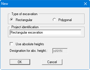
If you have just started the program an example well installation with an excavation (length = 64 m; width = 24 m) and 20 wells will be displayed on the screen after clicking the "Rectangular" button. The wells are arranged 1 m from the edge of the excavation. If a different installation was previously modelled the existing excavation dimensions and wells will initially be displayed on the screen.
For input of excavation dimensions of the example, select the "Edit/Excavation" menu item. You will see the following dialog box where you enter length and width of our excavation, and the distance of the wells from the excavation edge. Negative values are also allowed if, e.g., the wells are situated inside the excavation.
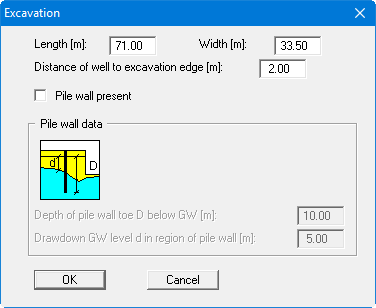
After confirming your input by pressing "OK" the program first performs a draft design and the results of this draft design are displayed in a message box. If you exit the message box the excavation is displayed on the screen with the new dimensions. If the excavation no longer fits on the screen due to the changes made, go to the menu item "Page size + margins/Auto resize" or, alternatively, press [F9]. The proposed wells will initially be displayed in the old position.
The excavation boundaries are displayed on the screen as a continuous line. The program will look for the "most unfavourable point" along the excavation edge, for calculation of the actual discharge. The line upon which the wells theoretically lie runs parallel to the excavation edge. This boundary is displayed with a dashed line. The wells need not necessarily be arranged on this line. However, this border will be used for calculation of the substitute radius independently of the actual position of the wells.