
The explanation will be for a rectangular excavation. With reference to excavations bordered with polygons, only minor deviations result, which will be handled in the following section. The main variables are contained in the following two figures.
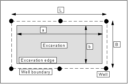
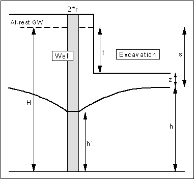
The range R can be defined in three different ways:
a) after Sichardt
![]()
b) after Kussakin
![]()
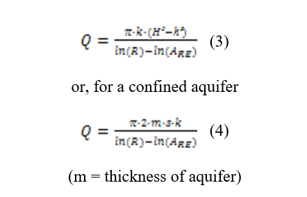
c) after Weyrauch
for unconfined aquifer:
![]()
for confined aquifer:
![]()
c) as fixed, which you enter yourself.
For small k-values, small drawdown and large excavations, a correction of the range R is necessary.
![]()
(ARE = substitute radius, see below)
It is your own decision as to when this correction should be used.
The drawdown value you wish to achieve is given with the values t and z. Together with the permeability k, the area of the excavation (+ distance of wells from the excavation edge) and the range R, the total discharge Qmax (formula 20 or 93 in HERTH/ ARNDTS) results from this drawdown.
The above two formulas are valid for values of:
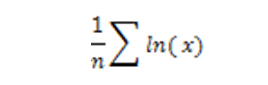
For values smaller than '1', instead of the expression
the relationship
is used.
The value Q contains possible surcharges for a faster achievement of the drawdown target (after HERTH/ARNDTS generally 10 %) and for possible imperfect wells (after HERTH/ARNDTS generally 10 to 30 %, but see also the critical notes by RIESS in the Grundbautaschenbuch).
The value ARE is the so-called substitute radius. The program contains all known possibilities for calculating the substitute radius.
a) ARE is calculated from

b) From a suggestion of Weber's, ARE is calculated from
(with ![]()
c) ARE is calculated from L/3 for elongated excavations, taking into account the drawdown at the centre of a row of wells.
d) ARE is calculated from L/5 for elongated excavations, taking into account the drawdown at the end of a row of wells.
e) ARE is user-defined
After entering the base data, the wells must be sensibly distributed around the excavation or the location and number of wells be determined by the program using the "Optimise" menu item.
The installation is then analysed. First, a follow-up calculation of the proposed installation is carried out, to find the most unfavourable spot on the edge of the excavation (see also HERTH/ARNDTS formula 18).
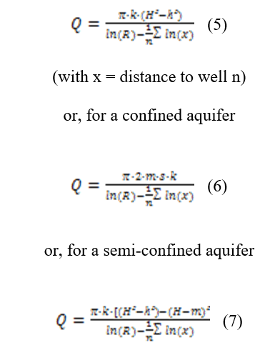
The program investigates the whole excavation border in 0.2 m steps and determines from this the most unfavourable point (MUP). The above 3 formulas are valid for an installation with wells of equal diameter. If varying well radii are present, the expression
is to be replaced by
In which q is the capacity of the corresponding well.
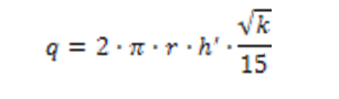
To avoid complex iteration, it is assumed in the program that all wells possess the same h'.
The actual water ingress to the excavation results from formula (5), (6) or (7). From this new, possibly larger Qmax, together with the selected number of wells, the minimum necessary well capacity (q) results. After this, the program determines the average well separation b', and from this - in case of activated "Wetted filter length after HERTH/ARNDTS" check box - the actual wetted filter length of the wells seb (formula 98 in HERTH/ARNDTS) or the current capacity of the wells.
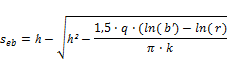
Alternatively, you have the possibility of deactivating the "Wetted filter length after HERTH/ARNDTS" check box and having the wetted filter length calculated for each well individually. The present wetted filter length then results from the well with the largest drawdown. Which of the two methods for calculation of wetted filter length is the theoretically correct one is disputed. In HERTH/ARNDTS all examples are calculated with the average well separation. In the 'Grundbautaschenbuch' (1997) however, RIESS criticises the dimensioning practice of HERTH/ARNDTS and favours the second method.
If the calculated wetted filter area is larger than, or equal to, the necessary wetted filter area (the capacity of a well results from this), the installation is sufficiently dimensioned. If this condition is not met, the program issues a warning message with notes on how to proceed further. You have the following possibilities:
-
Enlarge well radius
-
Enlarge well number
-
Enlarge well depth
After successful installation dimensioning, the program calculates the drawdown in the individual wells and the drawdown in the centre of the excavation or, for an excavation bounded by a polygon, in the excavation centroid. As, especially with excavations bounded by polygons, this is not the point with the least drawdown, an additional random generator is started, which then searches for the point with the least drawdown within the excavation.