
The following boundary conditions are given:
-
left system boundary immovable in x-direction,
-
right system boundary immovable in x-direction,
-
lower system boundary immovable in x and y-direction,
-
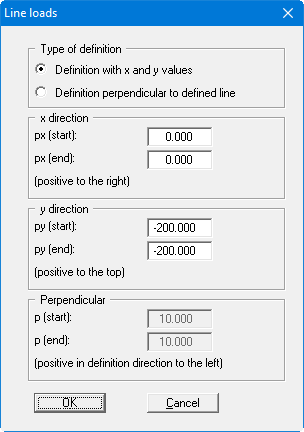
line load of 200 kN/m/m below the foundation.
Select the menu item "Boundary/(Displacement BC) In section".
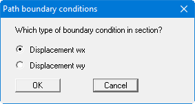
Conform the "Displacement wx" with "OK". Trace the left boundary nodes and set the displacement in x-direction to "0".
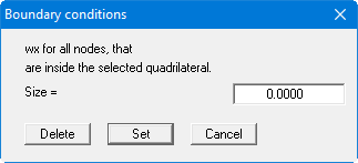
Repeat this for the lower and the right system boundaries. Select the menu item "Boundary/(Displacement BC) In section" and activate the check box for displacement boundary conditions in y-direction. Assign the lower system boundary a displacement in y-direction of "0".

Select the menu item "Boundary/Line loads" and click on the foundation centre and the right foundation edge. After pressing the [Return] key, define the foundation stress at 200 kN/m² via definition with x and y values.
Select the "FEM mesh/(Refine) All" menu item once again, to get a finer FEM mesh. You should now have a system with 384 triangles and 217 nodes (see "System/Info" menu item).