
The dialog box shown in the examples opens. First, select the equation for calculating the bearing capacity in the combo box. In addition to the standard DIN 4017:2006 and DIN 4017 (old) methods, the methods after Terzaghi, Meyerhoff, Hansen and Vesic well known from many literature references may also be selected. If the Terzaghi, Meyerhoff, Hansen or Vesic analysis methods are adopted, the English designations can be used in the bearing capacity equations in addition to the German designations.
You must then specify whether analysis will use the partial safety factor concept to EC 7 or DIN 1054:2010 or the old global safety factor concept. Decide whether you want to analyse a pad footing (rectangular or circular/annular footing) or multiple footings of a certain type (with footing analysis diagram).
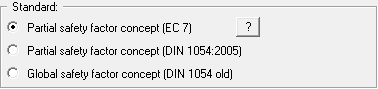
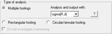
With the introduction of EC7, the table value "Allowable bearing pressure" used in the tables for spread footing analyses is generally replaced by the table value "Bearing resistance design value". Differences to DIN 1054:2010 in terms of footing dimensions do not result from this. If you are working to EC7, "sigma(R,d)" for design and output is activated.
DIN 1054:2010 states that an overturning analysis may be dispensed with for Load Case 3 if sufficient bearing capacity has been demonstrated. This rule is no longer included in Eurocode 7; it is therefore always necessary to perform an overturning analysis. In justified exceptional cases, however, the analysis may be turned off using the "Do not investigate overturning" check box.
The next part of the dialog box is only active if you are analysing using global safety factors. Here you can specify whether the reference parameter for safety is the "Load" or the "Shear coefficients" (friction angle and cohesion). In this case you must enter a safety factor for both the friction angle and the cohesion (see menu item "Edit/System parameters").
When analysing a single footing you can activate consideration of vibrodisplacement compaction according to Priebe using the "Use" check box in the Vibrodisplacement compaction group box (Heinz J. Priebe, Die Bemessung von Rüttelstopfverdichtungen, Ground Engineering, December 1995).
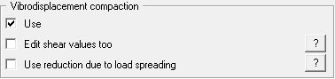
It is then possible to enter corresponding parameters for the improved soil layer (see menu item "Edit/Soils"). If the friction angle and cohesion are also to be adjusted, additionally activate the "Edit shear values too" check box.
Vibrodisplacement columns below the footing are usually only produced in a limited area called improvement area A1. With increasing depth areas outside the improvement area A1 are also used for load transfer due to load spreading. To compensate for this effect, the following reduction can be considered:
n = 1 + (n - 1) · A1 / A2 (n = improvement value according to Priebe)
At the footing base (= depth 0), the load area A2 corresponds to the footing area. With increasing depth, A2 increases due to an increase in area on all sides with an assumed load spreading angle
of 2:1.
If the "Use absolute heights" check box is deactivated, the ground level will be at 0.0 and all depth input is positive downwards. If the check box is activated, enter the layer depths, the groundwater level and the footing base in absolute values (y-axis positive upwards), e.g. in m AD. The designation for the absolute elevation, which you enter below (here: m AD), is shown in the soil properties legend as the depth dimension. Absolute ground level is entered in the "Edit/Ground level" dialog box.
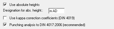
DIN 4019 Table 1 allows correction coefficients kappa to be taken into consideration for modelling settlements. These correction coefficients can be activated using the appropriate check box in the dialog box.
DIN 4017:2006 describes a new punching analysis method. To use this new analysis method the "Punching analysis using new method (recommended)" check box is activated by default when the program starts. This means it is now only necessary to specify whether a flexible footing is being dealt with in the "Edit/System parameters" dialog box (see Worked examples “Enter system parameters (Example 1)”.
If you wish you can enter a description of the problem being worked on in this dialog box; this will then be used in the General legend (see menu item “Graphics preferences/General legend”). Otherwise, the project identification is entered using the menu item "Edit/Project identification".
After confirming your input with "OK" you will see an info box corresponding to your safety concept with the safety factors or partial factors for the various load cases. Close the box by clicking on the load case of your choice. The safety factor values are automatically used in the system data. If the partial safety factor concept is adopted, the load case can be modified at any time using the "Edit/Partial safety factors" menu item). If a different load case is required when carrying out an analysis using the global safety factor concept, proceed via the "File/New" menu item.