
Once you have entered all data required to fully describe the system it can be analysed. For a "Steel pile" you will see the following dialog box. You can also initiate the analysis using the [F5] function key.
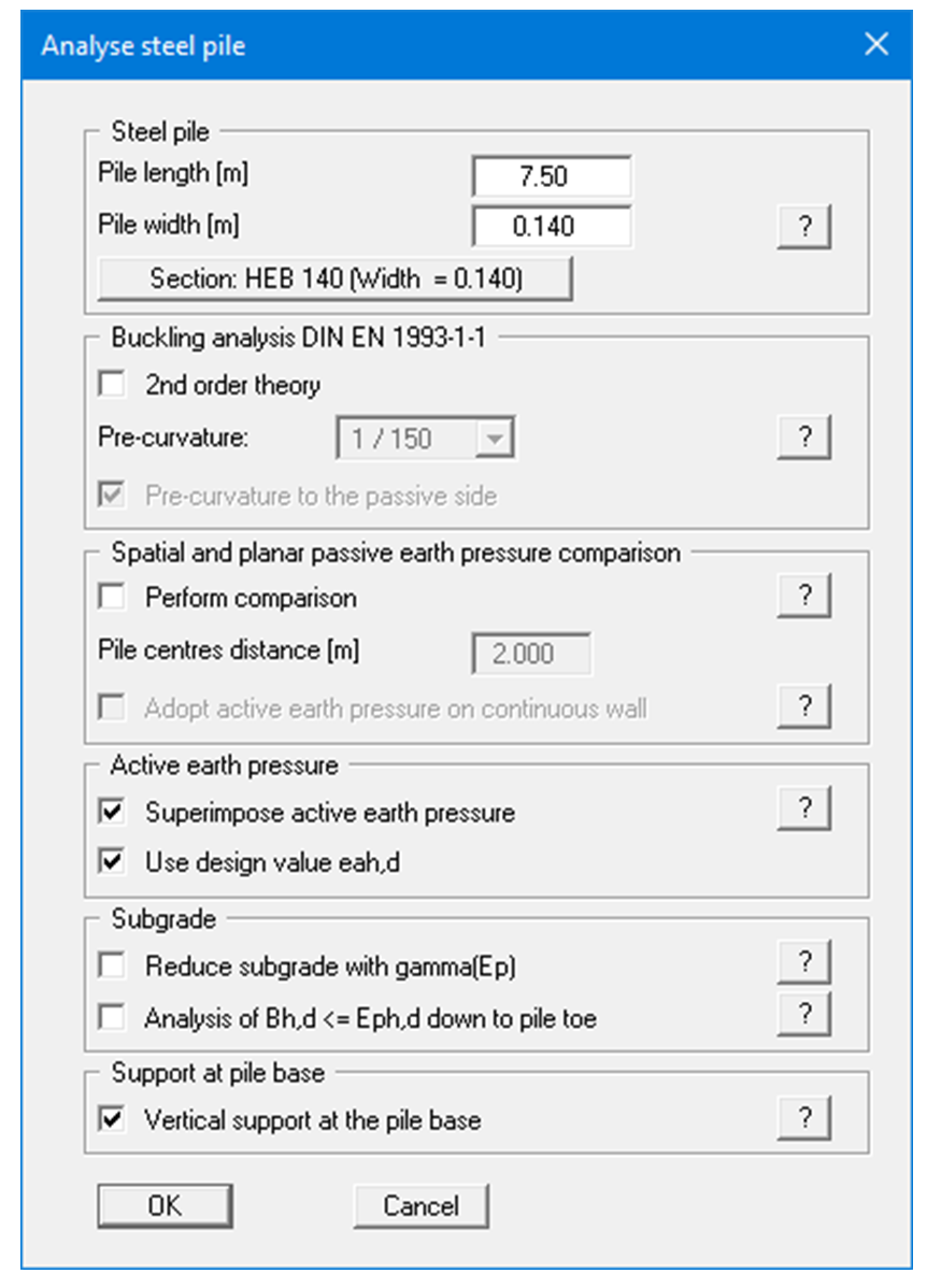
Pile length and pile width have already been entered using "Editor 1/System input" in accordance with your input. You can edit the data here to suit your needs. The three-dimensional passive earth pressure is calculated using this pile width. This value may deviate from that of the beam if the steel pile is placed in a pre-drilled bore and is subsequently concreted.
Using the button with the name of the selected steel section, i.e. "Section: ….", you can now select a different section as the design section via the usual option box. If you are analysing a "Bored pile", you enter the "Pile diameter" in the dialog box for subsequent design of the reinforced concrete cross-section.
Piles subject to buckling hazards can be analysed using "2nd order theory". A system pre-curvature, which can be adopted at 1/150, must be defined for buckling analysis to DIN EN 1993-5 or DIN EN 1993-1-1. The direction of pre-curvature must also be defined (to the passive side or the active side). Whether a pre-curvature towards the passive side or the active side provides the more unfavourable design values is system-dependent: it is therefore absolutely vital that both directions are investigated in a buckling analysis (see "Theoretical principles/2nd order theory").
EC 7 requires that a verification be performed to demonstrate that the soil stress (ks · w)d is smaller than the characteristic passive earth pressure eph,k (not reduced by a partial safety factor!). However, once analysis is complete it must be verified that the sum of the soil stress is smaller than the design passive earth pressure:
If the check box is deactivated, Bh,d and Eph,d are only cumulated to the pile pivot.
In some systems, tensile forces can occur at the pile base.This is due to the vertical immovability of the wall toe generated by the program.In bedded systems this boundary condition can be deactivated.However, when adopting the subgrade reaction modulus definition it is necessary that a tangential subgrade with the factor "µ(ks)"<> 0.0 is defined.The resulting normal force at the pile base is then more realistic.The value of "µ(ks)" generally has no great influence on the analysis results.The "Vertical support at the pile base" check box should only be deactivated if tensile forces occur at the pile base when the check box is activated!
After leaving the dialog box with "OK", the program checks whether the passive earth pressure is smaller than the resulting soil pressure from the elastic analysis, which is not permitted. In this case you see a dialog box for adjusting the subgrade reaction (see further explanations in the worked example).
Following the analysis, you can immediately carry out the design after confirming at the prompt. You then move directly to a dialog box, which can also be reached via the "System/Design defaults" menu item.