
You can enter a new system using this menu item. You will see the following dialog box:
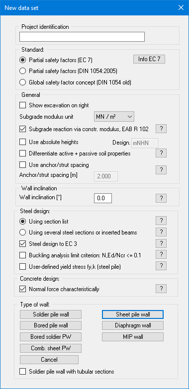
You can enter a dataset description ("Project identification") of the problem going to process, which will then be used in the General legend (see menu item “Graphics preferences/General legend”). This can be particularly useful when you are working with the menu items "Construction phases/Select files" and "Editor 2/Predeformation preferences". Using these program functions previously saved datasets are appended to the current dataset. The existing project identifications are also shown in the appropriate dialog boxes to aid file characterisation.
In the next group box, the radio buttons are used to specify which safety concept to use for analysis and design. Additionally,
In the next group box, use the radio buttons to decide which safety concept should be used for your calculation and design.
Excavation visualisation to the right can be activated, as well as selecting kN/m³ or MN/m³ as the units for the modulus of subgrade reaction via a drop-down menu. If the wall base is to be calculated with elastic bedding, a subgrade reaction modulus curve must be specified. When the program starts, the "Subgrade reaction via constrained modulus to EAB EB 102" check box is activated. The subgrade reaction moduli are then determined using the constrained modulus entered in the "Editor 1/Soils" menu item. If you wish to enter the subgrade reaction modulus course yourself, deactivate the above check box and enter the appropriate course in the menu item "Editor 2/Subgrade reaction moduli".
If you select the "Use absolute heights" check box, you can enter all depths or heights in m AD (heights are positive upwards). If this check box is not selected, the top of the wall is assumed at 0.0 (height/depth) and all further entries, depth of soil layers, for example, are positive downwards. If, however, you want to work with absolute heights, enter the appropriate depths correspondingly altered. Thanks to WYSIWYG there is no danger of using incorrect data since all input is immediately visible on the screen.
If your system uses differing soil properties on the active and the passive sides, activate the "Differentiate active + passive soil properties" check box in the above dialog box. You will then be presented with different input columns for entering the active and passive friction angle and unit weight soil properties in the "Editor 1/Soils" menu item. For better visualisation you can define the soil colours on the active and the passive sides differently using the Soil properties legend (see menu item “Graphics preferences/Soil properties legend”).
If the "Use anchor/strut spacing" check box is activated the anchor or strut forces are output in [kN] and no longer in [kN/m]. Input in terms of EA and EI are also no longer entered per metre.
Below this, a wall inclination between -6° and +6° can be defined. Please read the information displayed after pressing the "?" button.
The "Steel design:" group box offers a list of supplied sections (soldier pile sections, sheet pile sections, etc.) for subsequent design. The section list is loaded automatically when the program starts. Sections from a variety of well-known manufacturers can be accessed here. Clicking the "?" button will display further information.
If you activate the "Using several steel sections or inserted beams" check box instead of the section list, you can allocate different sections when designing sheet pile walls, soldier pile walls and combined sheet pile walls in a retaining wall (see Partial Corrosion Example). For bored soldier pile walls, diaphragm walls and bored pile walls, an inserted I beam can be defined at the top of the wall, which you select from the soldier pile wall section list via the then active "Editor 2/Inserted beam" menu item.
Steel design should always follow EC 3.
If the normal force is a compressive force, concrete design using the normal force design value is not on conservative. If the "Characteristic normal force" check box in the "Concrete design:" group box is activated, design is performed using the characteristic normal force.
The buttons in the bottom section of the dialog box allow you to select the type of retaining wall you wish to analyse. Having selected a type of wall and entered all the data necessary for its analysis, you can subsequently return to this menu item and select another type of wall. GGU-RETAIN maintains the data already entered, which can be used to analyse the new type of wall.
If the safety concept has been altered using the "File/New" dialog box, the dialog box for specifying either the safety factors or the partial factors always opens after leaving the dialog box by clicking "OK". These dialog boxes can also be accessed via the menu items "Editor 1/Verifications/Safety factors" or "Editor 1/Verifications/Partial factors". Verifications and safety factors can be modified at any time using these menu items.