
The coordinates of existing nodes can be edited. Three options are available for this:
-
"Via a table"
You can edit the coordinates of existing nodes or, alternatively, enter the coordinates of new nodes.
If you need to edit the current number of nodes click the "x FEM nodes to edit" button and enter the new number of nodes. You can navigate through the table using "Forw." and "Back". If you are working a problem using the subgrade reaction modulus method, each new point is assigned the default subgrade (see "Subgrade/Default subgrade" menu item). If you set the number of nodes to 0 the FEM incidence table is deleted.
It is even easier to import node coordinates via the Windows clipboard. For example, if the x-/y-coordinates of the FEM mesh nodes are available in an Excel table, it is possible to copy the two columns containing the data into the clipboard ("Edit/Copy") and then to paste them into the dialog box "Via a table" by pressing "Import clipboard". -
"Via equation"
If you have entered the coordinates using the wrong scale, for instance, you can correct this using this menu item.
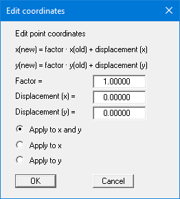
You also have the option of applying the factor for one direction only. Activate the required option button.
-
"In section"
If you have created your FEM mesh and subsequently want to move several nodes, click 4 points counter-clockwise with the mouse. In the following dialog box, you can then enter a desired displacement in x- or y-direction, for example.
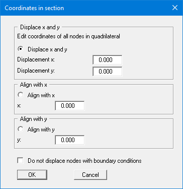
If you find that your nodes do not all lie on one line, you can have the nodes you have surrounded with your quadrilateral aligned with a specific x- or y-value.
If the "Do not displace nodes with boundary conditions" check box is activated these points will be excluded from any displacement.