
You can use the left mouse button to define a new node or the right mouse button to delete a previously defined node. This menu item can also be reached using [F3]. If you are working a problem using the subgrade reaction modulus method, each new point is assigned the default subgrade (see "Subgrade/Default subgrade" menu item).
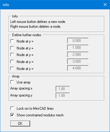
When defining nodes the x- and y-coordinates of the current mouse pointer position are shown in the status bar. Using the settings in the "Define further nodes" group box in the dialog box it is possible to automatically define up to 5 additional nodes at the same x-coordinate with a single mouse click, but with user-defined y-coordinates. In order to specify the nodes at defined locations, activate the "Use array" check box.
If you have access to a scanner you can scan in the system to be processed and save it as a bitmap file (extension: ".bmp"). This bitmap can be displayed on the screen using the Mini-CAD program module (see the "Mini-CAD" manual). This greatly simplifies input of the principal system nodes. Alternatively, you can also import a DXF file using Mini-CAD (see "Mini-CAD" manual). This can contain the system outline, for example.
If Mini-CAD data are already present, the initial dialog box provides a check box with the option of locking on to Mini-CAD lines. If you activate this check box, the mouse cursor appears as a rectangle with cross-hairs. If the end point of a Mini-CAD line is located within this rectangle the program will lock on to this point precisely; if a number of points are located within the rectangle, it will lock on to the one nearest the centre of the crosshairs.