
Definition of the FEM mesh follows the same procedure described for the subgrade reaction modulus method. Please read Section “Procedure for the subgrade reaction modulus method” first. The "Subgrade" menu is now replaced by the "Constrained mod." menu.
It is necessary to define a triangle mesh for an analysis using the constrained modulus method. This mesh is not related to the FEM mesh. The nodes of this triangle mesh are formed by drilling points. The drilling points are connected to form a triangle mesh, allowing the program to interpolate the constrained modulus profile at each point. Proceed as follows to define the drilling points:
-
First select the menu item "Constrained mod./Layers". You can edit the soil properties and the number of layers in the dialog box. Click the "Edit number of layers" button and enter the new number of layers.
-
You should then (not absolutely necessary) go to the menu item "Constrained mod./Default depths". If you have defined three layers in "Constrained mod./Layers", this dialog box displays three layer depths. The associated soil properties are also listed for your information. The depths given can be edited to suit your requirements. The depths are given as depths in metres below grade (m bg). When subsequently defining triangle nodes these layer depths are assigned to the corresponding node. You can then edit the layer depths as required for each node. However, if the constrained modulus profile is the same for almost all nodes of the triangle mesh, you can save some input effort by initially defining default depths. If you click the "For all" button, all existing triangle nodes are assigned these depths.
-
After making these preparations you can specify the locations of triangle nodes (drilling points). A coordinate system is visible on the screen. If the field of view does not correspond to your basic system go to the menu item "Page size + margins/Manual resize (editor)" and enter the values for your system in the dialog box.
-
Then go to the menu item "Constrained mod./Define nodes" (not "FEM mesh/Define nodes"!). Using the left mouse button, click the triangle nodes (= location of points at which the constrained modulus profile is known). The current coordinates of the tip of the mouse pointer are shown in the program window title bar. Input entered by mistake can be undone by right-clicking the node. If you press the [ESC] or the [F2] key, the screen is refreshed and you will see a graphical representation of the constrained modulus profiles.
-
If this representation appears too small or too large, go to the "Constrained mod./Preferences" menu item and adjust the factors for representation of the constrained modulus profile width and depth to suit your needs.
-
Alternatively to coordinate input using the mouse, you can enter the values in a table. To do this, select the menu item "Constrained mod./Edit".
-
After node input you can edit the depths of the of the individual layers at the nodes. To do this, select the menu item "Constrained mod./Edit layer depths". Once this is done, a double-click near a node is sufficient to open the following dialog box:
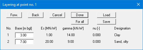
This box is absolutely identical to the box for the default depths. The only difference is that any alterations are with regard to the current node. The depths are given as depths in metres below grade.
-
Once you have defined at least 3 nodes (drilling points) you must connect these nodes to a triangle mesh in order to allow the program to carry out interpolation during the analysis. You have two options:
"Constrained mod./Manual mesh"
Click three nodes to create each respective triangle. Mistakenly entered triangles can be deleted again by clicking the three nodes.
"Constrained mod./Automatic"
The program carries out a so-called triangulation and connects all triangles to form a triangle mesh. Even after this you still have the option of deleting triangles by clicking the three nodes of a triangle using "Constrained mod./Manual mesh". If a triangle mesh already exists, you will be asked before triangulation whether you want to delete this mesh. Only press the "Supplement" button in exceptional cases. The triangulation follows certain laws which may not allow sensible enhancement of an existing partial mesh.
The constrained modulus method requires an iteration process, in contrast to the subgrade reaction modulus method. In the first step, the settlements at all FEM mesh nodes resulting from a constant load of 1 kN/m² on the FEM elements are calculated. To do this, the Boussinesq equation is numerically integrated, because there is currently no analytical solution to this problem. The pressures exercised on the nodes (in the first step = 1 kN/m²; in all following iteration steps = ks · w) are divided by the calculated settlements in order to acquire the subgrade reaction modulus for each node. Following this a calculation is performed using the subgrade reaction modulus method including determination of the node displacements. If the slab differential settlements deviate from the user-defined settlement given at the start of analysis, the iteration is continued.
The constrained modulus method employs a limiting depth corresponding to the base of the
constrained modulus profile. Alternatively, the limiting depth can be calculated to DIN 4019. To do this, the appropriate check box must be activated in the "System/Analyse" dialog box.