
Now go to the menu item "Constrained mod./Define nodes" (not in the "FEM mesh" menu!) and click four points, located roughly at:
-
constrained modulus profile 1 at x = -1 and y = -1,
-
constrained modulus profile 2 at x = -1 and y = +4,
-
constrained modulus profile 3 at x = +11 and y = 2,
-
constrained modulus profile 4 at x = +11 and y = 7
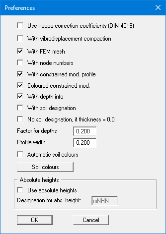
These coordinates ensure that all of the slab's nodes are included. Using the menu item "Page size + margins/Auto-resize" or, more simply, by pressing [F9], a screen-filling representation can be achieved if the point in question lies outside of the current view. The drilling points (constrained modulus profile) are displayed parallel to input with the mouse. The profiles look a bit rough in comparison to the slab. If necessary, correct the optics by going to the menu item "Constrained mod./Preferences" and making the following input:
Now connect the four constrained modulus profiles to form a mesh. To do this, go to the menu item "Constrained mod./Automatic (mesh)" (not the "FEM mesh" menu!).