
If you have already generated the immovable boundaries at the left and right of the system using the array function while defining the FEM mesh, you may skip this step.
Otherwise, go to the menu item "Boundary/In section (displacement)".
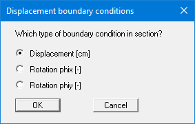
Activate the "Displacement [m]" option button and leave the box using "OK". Then encompass the left 5 nodes of the system with the quadrilateral. The following dialog box then opens:
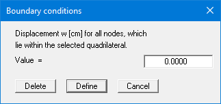
Press the "Define" button. This assigns a vertically immovable support to the left boundary. Do the same for the right 5 systems nodes. The free boundaries at the top and bottom slab faces do not need defining separately. The case of a free-earth support applies at all boundaries at which no action or displacement boundary condition is defined.
If you define your FEM mesh using the "FEM mesh/Array" function you can specify immovable boundaries in the preferences for the node array by activating the corresponding option buttons for the sides required (see "Step 2: Define the FEM mesh").
If you wish, you can check the entered boundary conditions by pointing to the menu item "Boundary/Check".