
The program is based on:
-
Bishop (circular slip surfaces)
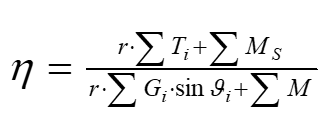
with
-
Janbu (polygonal slip surfaces)
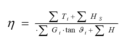
with
from DIN 4084. Where:
![]()
Gi self weight of an individual slice in kN/m with consideration of the soil unit
weight estimates from Table 1, including surcharges
M moments of loads and forces not included in Gi around the centre-point of
the slip circle in kNm/m, positive when acting excitingly (H for Janbu
analogous)
MS moments around the centre-point of the slip circle in kNm/m from forces
after Section 6e (DIN4084), which are not considered in Ti (HS for Janbu
analogous)
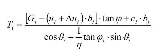
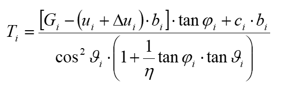
Ti the resisting tangential force of the soil at the slip surface for each slice in
kN/m (for polygonal slip surfaces the horizontal component)
![]()
equal to the polar coordinates
r radius of slip circle in m
bi width of slice in m
![]()
(DIN 4084)
ci the decisive cohesion, in kN/m², for the slice after Section 8 (DIN 4084)
ui the decisive pore water pressure, in kN/m², for the individual slice
![]()
consolidation. In the GGU-STABILITY program, ui is calculated by multiplying
the pore water pressure coefficient and the effective vertical stresses.
Alternatively, you have the possibility of defining so-called consolidation
layers. Using the required input data, the program carries out a one-
dimensional consolidation calculation.
The relationships are described in detail in DIN 4084 and DIN 4084:2009. We need therefore only deal with a few special cases here. Partial factors are used in DIN 4084:2009. The safety factors are thus already incorporated in the soil properties, loads, etc. The term "safety factor" is thus already allocated. Instead of " ![]()
For pre-stressed tension members, the friction force activated by the normal component may be considered, in accordance with DIN 4084 and DIN 4084:2009 (Section 7.2.3.3). This is implemented for tension members in GGU-STABILITY.
In DIN 4084:2009, Section 7.2.3 the term self-tensioning is defined. The angle ψA between the tension member axis and the slip surface is decisive for this (see Figure 2 in DIN 4084:2009). This condition is calculated by the program (only when DIN 4084:2009 or EC 7 is specified). The value for ψA can be entered for each soil in the menu item "Editor 1/Partial factors...".
In DIN 4084:2009, Section 6.2.3 it is proposed that for pre-stressed tension members which are not self-tensioning, but which act favourably, the fixing force of the tension member and not the design value of the tension member is to be used into the calculation. If you design according to DIN 4084:2009, the program checks for non-self-tensioning and favourable, and then multiplies the design value of the tension member with a factor, which can be entered globally for all tension members in the menu item "Editor 1/Partial factors…".
For analysis according to DIN 4084:2009 the design values are to be entered for soil dowels, geosynthetics and tension members. For the soil properties you enter the characteristic values, from which the program calculates the design values using the partial factors.
During input, partial factors must be differentiated for drained and undrained soils. Correspondingly, a "drained" check box is provided for input of soil properties - except for analysis using the global factors to DIN 4084 (old) - so that the program can calculate the correct design value for each soil.