Pressing "Well casing" opens a dialog box for entering the well casing. In contrast to the gauge casing on the stratigraphic log the well casing layer data (= pipe lengths) are entered relative to the top of the casing (= top of pipe) and thus correspond to the actual pipe lengths employed. The subsequent casing visualisation width can be defined here separately for each layer.
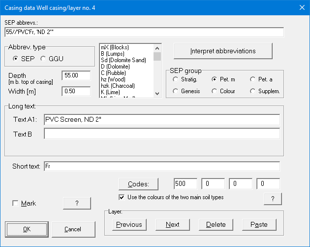
For well casings, the following pre-defined hatchings are available with the given code numbers:
-
500 Screen
-
510 Vertical lines
-
520 Horizontal lines
-
530 Cross hatching
-
540 Cap
-
550 Sump
-
560 Exterior line
If you would like to use special casing details in the profile, use the menu item "Preferences/Bitmaps". With this option it is possible to tie in drawings which you have created with a graphics program (e.g. Paintbrush).
In order to highlight special features during dismantling, you can underline the description of this layer in colour by activating the "highlight" button.
Activate the "Show backfill" check box to enter the backfill details and then click the "Backfill" button.
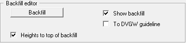
The same editor box as for entering backfill for a gauge on the stratigraphic log opens. However, it is also possible to define a separate backfill width for each layer of the well backfill. If you have activated the "To DVGW guideline" check box, all depth information is displayed on the left of the well log and the backfill and casing descriptions on the right.
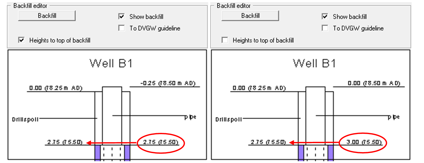
For graphical visualisation of the well casing, it makes sense to activate the "Heights to top of backfill" check box in the general editor box. If the layer depths are not specified as "Abs. height only", the relative heights of the casing and the backfill are shown relative to different starting heights. In the visualisation, different relative heights are then shown for the same heights, as demonstrated in the following example: