
The following dialog box opens:
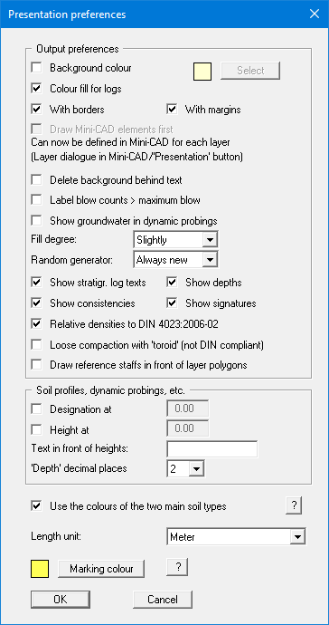
In the upper part of the dialog box, you can specify output preferences:
-
"Background colour"
You can optically enhance the drawing with a background colour. You can switch the background colour display on and off and select a colour using the button on the right. -
"Colour fill for logs"
The stratigraphic logs and well casings can be coloured according to DIN. Only the main soil types will be considered. Colour fill is possible if at least one of the first two code boxes contains a valid code (see Section 6.4.2). With two main soil types, the profile will be vertically divided. Additional details on divided colour display can be found further down in the description of the "Use the colours of the two main soil types" check box. You can alter the colours for each main soil type with the menu item "Preferences/Soil colours". The colour fill can be quickly switched on or off using the icon
-
"With borders"
If you deactivate this check box, the outer page borders will not be printed. To allow you to still see the true page size the switched off borders are shown on the screen as purple lines. This allows, e.g. together with a page format fitted to the printer, printing of a single log or similar to an A4 printer, without it being necessary to use an output zoom factor < 1.0. This can save subsequent enlargement on a copying machine (see explanations of 1:1 print output ). -
"With margins"
In the program's default setting the output sheet is shown with a frame around the drawing area. The distance of the frame from the sheet edge is defined in the menu item "Input/Page format". The frame can be switched off by deactivating this check box. -
"Draw Mini-CAD elements first" - This check box can no longer be selected!
Originally, you could influence the sequence of presentation using this button. Mini-CAD elements are in the default setting of the program above the elements you define via the "Input" menu, so can cover stratigraphic logs, dynamic probings, etc. From version 7 of the integrated Mini-CAD module you can now work on a total of 20 different levels. Place Mini-CAD objects that are to be drawn behind the elements of the main program on a separate layer. Click the "Layers" icon in the Mini-CAD pop-up menu and deactivate the required layer in the dialog box for the "Visualisation" button. The Mini-CAD elements of this layer are then drawn first, e.g. they are located behind your stratigraphic log.
Elements drawn with "Header CAD" can be placed behind the main graphics in the same way using the "Layers" icon, "Visualisation" button in the "Header CAD" pop-up menu.
-
"Delete background behind text"
If the text and the presentation overlap due to lack of space, the background can be deleted. However, beware of the visualisation sequence. Objects are drawn in the sequence they were created in. Objects drawn later are positioned in front of the previously drawn objects. If the background behind a text is deleted the texts still disappear behind subsequently defined objects. This can be seen in the figure below. The texts for S 1 disappear behind stratigraphic log S 3. The S 3 texts can be seen with deleted background in front of the S 2 log, because S 3 was the last stratigraphic log entered.
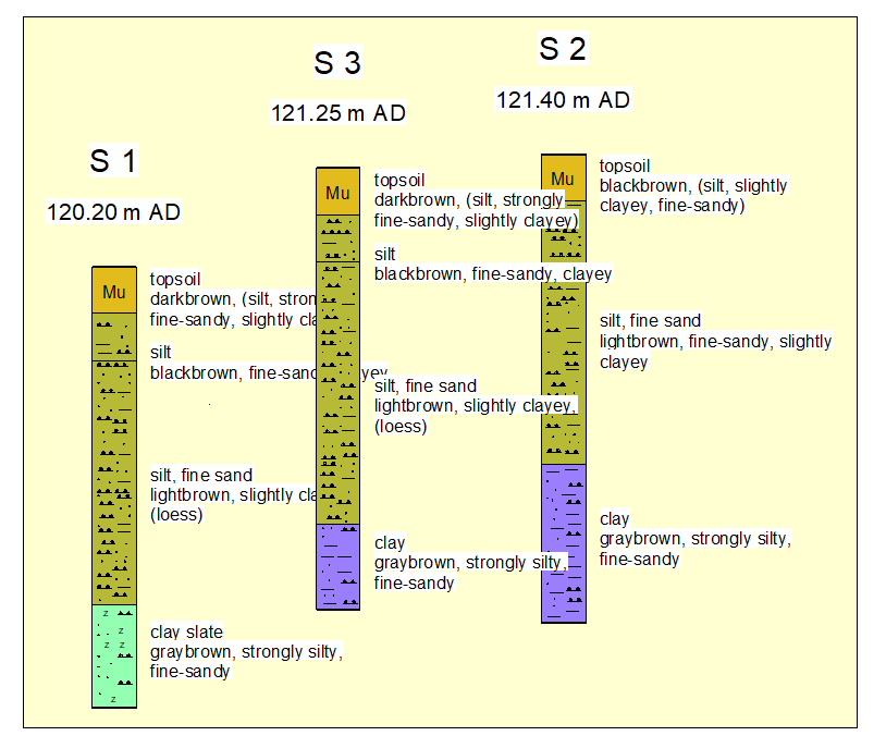
To change the order, you can copy and paste a stratigraphic log using the functions in the "Edit" menu. The copied stratigraphic log is now in last place in the order of presentation. Then simply delete the original stratigraphic log.
-
"Label blow counts > maximum blow"
If blow counts cannot be read from the dynamic probing diagram, because the blow count is greater than the defined maximum blow count, activate this check box. When activated, all blow counts over and above the defined maximum are shown as numbers beside the dynamic probing diagram. -
"Show groundwater in dynamic probings"
If you have given a groundwater level in the dynamic probings base data, you can have it displayed in the dynamic probing diagram by selecting this check box. -
"Fill degree"
Here you can select from a very slightly to a very strong filling of the stratigraphic logs with soil signatures. -
"Random generator"
Using the "Always new" setting the soil signatures are randomly redrawn at each screen refresh. -
"Show stratigr. log texts"/"Show depths"
"Show consistencies"/"Show signatures"
Using these four check boxes the respective visualisations on the stratigraphic logs in general can be switched off, i.e. in the screen display and in the print output. This can be useful for geological sections created using layer polygons, for example. Only the stratigraphic logs themselves, without any other annotations, are then shown on the layer blocks.
The signatures can also be switched off on the screen only to facilitate faster screen refreshing. Deactivate the "Screen display with soil signatures" in the "Graphics preferences/Preferences" menu item.
-
"Relative densities to DIN 4023:2006-02"
DIN 4023:2006-02 does not differentiate between loose and very loose compaction. If this check box is activated the same signature is used for both relative densities and the "Soil types and consistencies" legend adjusted accordingly. -
"Loose compaction with 'toroid' (not DIN compliant)"
If the DIN 4023:2006-02 check box is activated loose and very loose compaction can nevertheless be differentiated using this check box. -
"Draw reference staff in front of layer polygons"
If geological sections use layer polygons and are very wide, the reference staffs can be drawn in front of the layer polygons by activating this check box. In the default setting the reference staffs are behind all other elements.
In the "Stratigraphic logs, DPTs, etc." group box you can set the following preferences for the labelling of objects:
-
"Designation at"
By selecting this check box the names of stratigraphic logs, wells etc., will not appear directly above each object, but will all be displayed at the same height in the drawing. This height is to be given in absolute coordinates, e.g. in m AD. -
"Height at"
The positioning of height entries of objects is analogous to that of the designations (see above). -
"Text in front of heights"
If you enter e.g. "AD" in this box, the height labelling above the logs, tests etc. will be in the form of "AD + 12.34". -
"'Depth' decimal places"
Define the number of decimal places for stratigraphic log depth labelling.
In the lower part of the dialog box, you can specify the following preferences:
-
"Use the colours of the two main soil types"
In GGU-STRATIG the colours and soil signatures of all soil types specified in DIN 4023 are defined using code numbers, which are entered in the strata input editor. The main soil type soil colours are determined from the code numbers in the first two code boxes.
If there are two main soil types (= code numbers in the first two code boxes), the profile is colour-divided using the soil colours defined in the first two code boxes. This colour division can be subdued for all soil profiles by deactivating the "Use the colours of the two main soil types" check box. Only the soil colour resulting from the code in the first code box is then adopted for use.
Please note that when opening files created using GGU-STRATIG older than main version 10, the "Use the colours of the two main soil types" check box is inactive. When using these old logs, the program first checks whether there are two main soil types in long text line A1 (= two upper case soil type descriptors at the beginning and end of the line). Only then is the colour visualisation divided for two main soil types (= code numbers in the first two code boxes).
You can use the old method for editing these legacy files or activate colour division globally using the check box. If you confirm the query "Use old colours?" after activation, the "Use the colours of the two main soil types" check box is activated in all strata.
-
"Length unit"
The height and depth units can be specified here. -
"Marking colour"
Here you can specify a different marking colour with which you can highlight the description of a soil layer. Inform yourself about the button "?".
By clicking on "OK" the preferences will be accepted; with "Cancel" they will be rejected.