
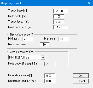
This menu item consists of the central data input for your system and the initial analysis data. You will see a dialog box, in which almost all the basic data necessary for analysis of the diaphragm wall can be entered.
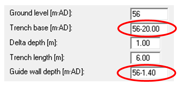
If you do not use absolute heights, ground level is assumed to be 0.0 m and all depth information is positive downwards. If you have activated the "Use absolute heights" check box in the "File/New" menu item, an additional "Ground level" input box will be displayed. All height input is then in [m AD]. To adapt the trench and guide wall depths to the new elevation, you can use the calculate function in the input boxes. Simply enter the new ground level elevation in front of the existing elevation data and let the program calculate and enter the new elevations by clicking "OK".
If the program exits the dialog box (see above) after converting and entering the altered elevations, you will first read a query on how to proceed with the remaining elevations.
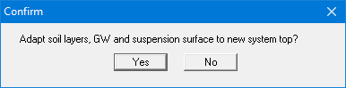
Normally, the elevations of the soil strata, etc., should be adapted to the new local datum ground level elevation. In the prompt box, then, click the "No" button. Adaptation would mean that the depth of a soil layer entered as a positive value would be converted from, for example, 7.5 m to an absolute height of -7.5 m AD. If, then, you only convert your system to [m AD], always select "No".
In the upper group box, you enter the dimensions of the diaphragm wall and the guide wall. The "Delta depth" defines the model points at which safety factors are computed. Distinctive points in the system such as the base of the guide wall and layer boundaries are always taken into consideration.
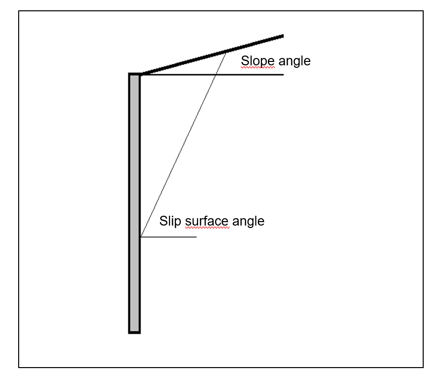
The range of variation of the slip surface angle is then specified.
The number of intermediate angles between the two slip surface angles ("minimum" and "maximum") is defined by the "No. of subdivisions". The program begins the analysis with the first entered minimum slip surface angle. The next intermediate angle is then investigated.
In the lower group box, you select the type of lateral pressure increase. There are three possible options:
-
bilinear after DIN 4126
-
sublinear after Terzaghi
-
sublinear after Terzaghi, but with the limitation that the bilinear approach after DIN 4126 using the bending point defined by the depth z = trench width is not exceeded.
When computing the lateral pressure increase after Terzaghi the lateral pressures increase following an exponential function. In order to model the curve precisely enough in the program, it is possible to control the model points at which the lateral pressures after Terzaghi are computed using the "Delta depth (Terzaghi)" value.
In the lower group box, any ground inclination and the value of the distributed load are defined.
In contrast to line loads, the distributed load is always taken into consideration when determining the friction forces acting on the wedge flanks.