
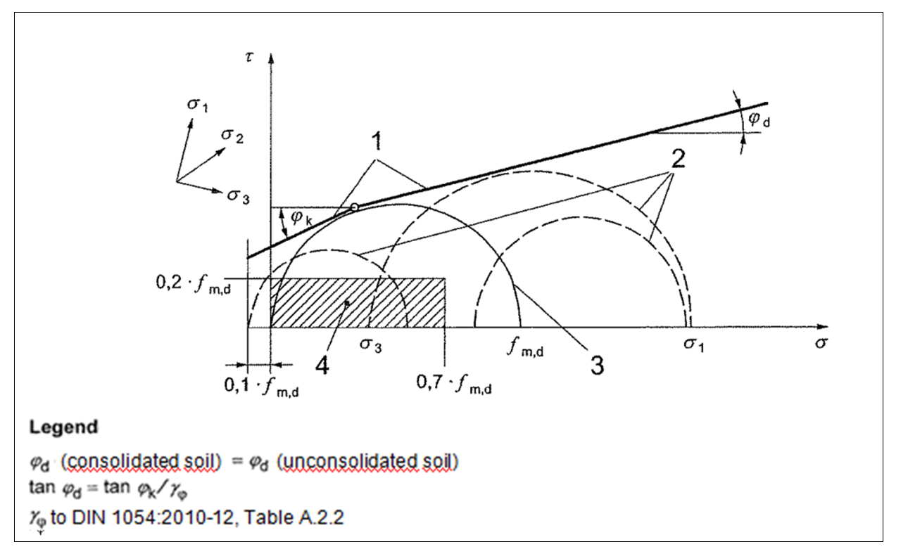
In the analysis using principal stresses the design values of the load may not exceed the stress states defined as allowable as shown in Figure 1 taken from DIN 4093.
The normal stress σy is distributed linearly across the cross section. The shear stress τ has a parabolic graph. The stress σx parallel to the cross section is approximately 0.0.
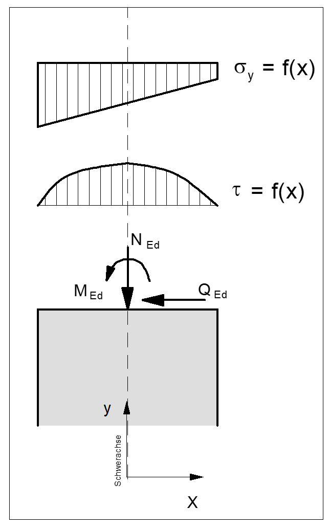
Using the variables σy, σx and τ the principal stresses σ1 and σ3 can be calculated for any point on the cross section
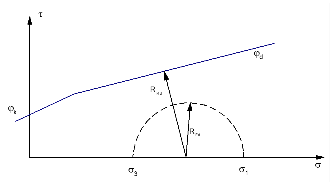
Figure 22 shows Mohr's circle for a major principal stress. The utilisation factor µ can be calculated using the radius REd of this circle and the distance RRd from the centre of the circle to the boundary line.
µ = REd/RRd