"Analysis options" menu item
Using this menu item, you can edit the default preferences of the current system. The dialog box corresponds to the box in the menu item "File/New" (see descriptions in section 8.1.1).
"System" menu item
A dialog box opens for defining the system:
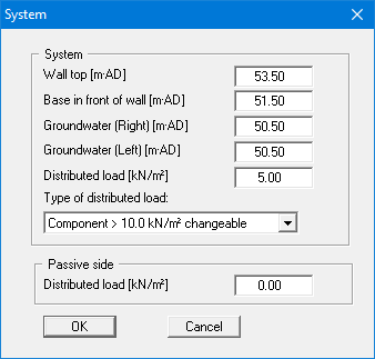
In the upper group box, enter the depth of the base in front of wall and the groundwater levels. If you checked the "Use absolute heights" box when defining the system, an additional entry, "Top of wall", appears in the dialog box for specifying the absolute position. In this case, all heights are measured in m AD or m site zero, i.e. the y-axis is positive upwards. You can then enter a value, for example, of 53.50 [m AD] in the "Top of wall" field. All further input must then be with reference to this value.
If the height of a previously defined system is subsequently set to absolute heights, a query follows after leaving the dialog box above asking for confirmation of whether soil strata and defined elements such as anchors, for example, should be adapted to the new wall. Adaptation would mean that the depth of a soil layer entered as a positive value would be converted from, for example, 7.5 m to an absolute height of -7.5 m AD. If, then, you only convert your system to [m AD], do not select any elements in the query box and press the "OK" button.
Moreover, a distributed load can be defined. Using the global safety factors, you will see here the "Distributed load as live load" check box. This is only of interest for verification of deep-seated stability. If the distributed load is defined as a live load, this load will only be adopted for verification of deep-seated stability if it acts excitingly.
If you are working with the partial safety factors, decide whether the distributed load is "Permanent", "Changeable" or the "Component above 10.0 kN/m² changeable" (see the dialog box above). "Component above 10.0 kN/m² changeable" means, for example, that for an input of 13.5 kN/m², 10 kN/m² are adopted as permanent and 3.5 kN/m² as changeable in the analysis.
"Body (general)" menu item
Enter the loads acting on the gabions, the footing length, base inclination and friction coefficient. A more detailed description can be found in "First steps", section 6.1.4.
"Body (geometry)" menu item
Data input for the body geometry is carried out in horizontal sections. In the dialog box, define the respective depths of the horizontal sections and the two corresponding x-values of the gabion wall. For example, if you need to enter a gabion wall consisting of 2 elements (height = 0.5 m, width = 0.8 m) with a horizontal displacement of 0.1 m, you must define 4 horizontal sections.
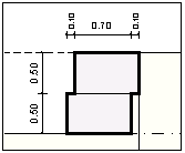
Figure 20 Body geometry
The corresponding data input is:
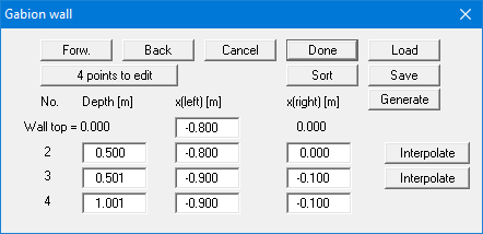
In the displacement area you define a small jump of, e.g., 0.001 m.
For most practical cases input can be automatically generated using the "Generate" button (see "First steps: Worked example 1/Step 4", section 6.1.5). In this way a gabion noise abatement wall can be very quickly generated, and the program automatically adapts the wind load and soil properties, among others, corresponding to your input (see "First steps: Worked example 2 / Step 1", section 6.2.2).
"Material" menu item
Enter the properties for the gabion material and for verification of the unreinforced concrete.
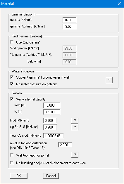
A more detailed description can be found in "First steps" (section 6.1.6) and in the "Theoretical principles" (section 7.25).
"Berms (active side)" menu item
You can define a maximum of 20 berms on the active side.
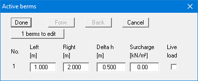
Enter the x-ordinates of the toe and head of the berm. With "delta h" you define the height of the berm; whereby negative values are also permitted. Finally, a "Surcharge" on the horizontal surface behind the head of the berm can be entered.
If more than one berm is present in the system, click "x berms to edit" and enter the number of berms.
Berms may not overlap. The program checks that this condition is adhered to and warns of any errors.
"Berms (passive side)" menu item
Berms on the passive side are defined in the same manner as for the active side.
"Soils" menu item
You can define the soil properties in the following dialog box:
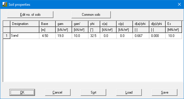
Using the "Common soils" button, you can easily select the soil properties of many common soils from a database or determine intermediate values. In the dialog box, which you open by pressing the "Common soils" button, open the "Soils_english.gng_ggu" file when first starting the program in English ("Edit table"/"Load" buttons). Then save the data set in the "Soils.gng_ggu"
file on the program level in order to open your modified database file when the program starts.
You can also enter your own data ("Edit table"/"x soils to edit" button) and save it in the "Soils.gng_ggu" file. You can also use your adapted file in other GGU programs by means of
the "Common soils" function if you copy the file into the appropriate GGU program folder.
Layer depths are always with reference to the top of the wall, or are absolute heights (m AD), if this was selected in the initial dialog box of the "File/New" menu item.
According to EC 7, section 6.5.2.2 the passive earth pressure must be calculated with a wall friction angle = 0 when analysing the bearing capacity. If you have activated the "Differentiate active + passive soil properties" check box in the dialog box in "File/New" or "Editor 1/Analysis options", you can enter differing friction angles and unit weights for the active and the passive sides.
In stratified soils the number of layers must be entered under "Edit no. of soils". Clicking the "Sort" button sorts the soil layers according to depth; however, this is performed automatically when you click "OK" to leave the dialog box. This eliminates the possibility of input errors. You can also use this function to eliminate a soil from the table. Simply assign the soil to be eliminated a greater layer depth and then click the "Sort" button. The corresponding soil is now the last soil in the table and can be deleted by reducing the number of soils.
"Type of earth pressure" menu item
In this dialog box you define the type of earth pressure on which the analysis is to be based.
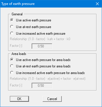
The options for area loads can be specified separately.
"Active earth pressure" menu item
You can specify active earth pressure preferences using this dialog box:
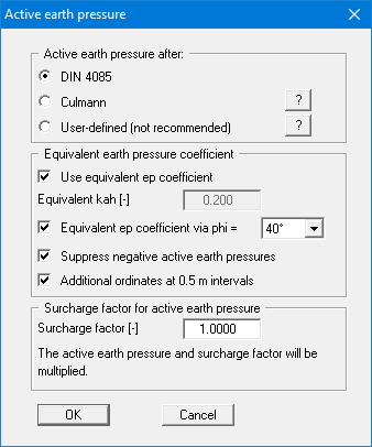
In the upper group box you specify the type of active earth pressure calculation. If the "Culmann" check box is activated the active earth pressure is calculated after Culmann using a slice method with straight slip surfaces.
The "Use equivalent ep coefficient" check box should only be deactivated in exceptional circumstances (see EAB R 4). The equivalent earth pressure coefficient can only be smaller than 0.2 in special circumstances (see EAB R 4). It only makes sense to deactivate this check box when re-examining existing analyses (for instance, all the examples used in the Piling Handbook). Alternatively, the equivalent earth pressure coefficient can be defined by means of a friction angle phi = 40°. This procedure also takes the defined wall friction angle into consideration.
Several applications on the market also provide the option of a general increase in active earth pressure, apart from certain forms or earth pressure redistribution. In order to be able to check calculations performed with such an application, GGU-GABION also offers this possibility.
"Passive earth pressure" menu item
You can specify passive earth pressure preferences using this dialog box:
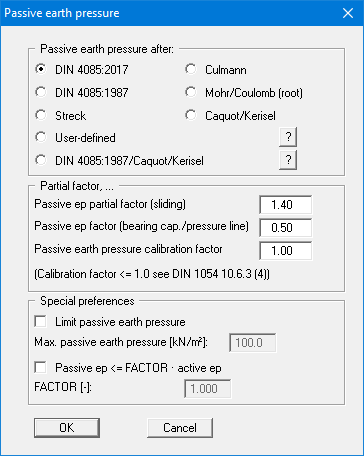
In the upper group box you specify the type of passive earth pressure calculation. If the "Culmann" check box is activated the passive earth pressure is calculated after Culmann using a slice method with straight slip surfaces.
When you calculate intermediate construction phases large embedment depths may result, with large passive earth pressures for comparably small active earth pressures. This allows the location of the pressure line in the lower section of the wall to be displaced far to the earth side and even to leave the kernel width. In such situations you can limit the passive earth pressure to a user-defined value in the "Special preferences" group box and thus suppress the displacement of the pressure line.
"At-rest earth pressure" menu item
Using the at-rest earth pressure function, the area loads are calculated by increasing by the factor k0/kah in compliance with DIN 4085:2011 section 6.4.3.
Alternatively, it is possible to determine the demands placed on the wall by area loads according to the theory of elastic half-space. The required concentration factor is specified in the following dialog box, if the upper check box is activated.
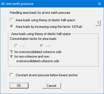
For gabion walls with at least two geogrid layers, at-rest earth pressure can be kept constant from the lowest layer (= anchor). This setting can be achieved by activating the check box at the bottom of the dialog box.
"User-defined earth pressure coefficients" menu item
If you want to work with user-defined earth pressure coefficients instead of with those computed by the program you can enter them here. Enter the coefficients for horizontal ground. If necessary, GGU-GABION will convert them for sloping ground using equation values for kah0 and kah (see "Theoretical principles/Berms", section 7.7).
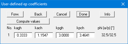
If the "Compute values" button is pressed the earth pressure coefficients can be calculated by the program in accordance with the required standard and slope angle.
"Verifications/Safety factors" menu item
If you are analysing with global safety factors to DIN 1054 old, you can specify the verifications to be performed by the program by activating the corresponding check boxes in the dialog box shown below.
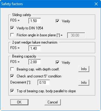
Then enter the safety factors for the individual verifications. The program's default values in the box are those required by the DIN 1054. If you do not want the program to perform the verifications, the corresponding check box must be deactivated. Pressing the two "Info" buttons, you will see further information.
"Verifications/Partial factors" menu item
If you are analysing with the partial safety factor concept , you will see the following dialog box for defining the partial factors.
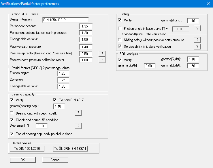
In the "Default values" group box the partial factors for the various load cases and subsoil conditions given in the DIN 1054:2010 and in the EC 7 can be selected by means of the dialog box reached by clicking the "To DIN 1054:2010" button. The selected design situation is automatically entered at the top of the dialog box and shown later in the General legend. However, you can also use your own designations. The load case designations were altered for the EC 7 partial safety factor concept:
Load Case 1 is now DS-P: Persistent Design Situation
Load Case 2 is now DS-T: Transient Design Situation
Load Case 3 is now DS-A: Accidental Design Situation
In addition, there is a seismic design situation (DS-E). In the DS-E design situation all partial factors = '1,0'. It is also possible to select the partial safety factors compliant with Austrian standards using the "To ÖNORM EN 1997-1" button.
The "EQU analysis" group box (limit state of loss of static equilibrium) is only available in EC 7.
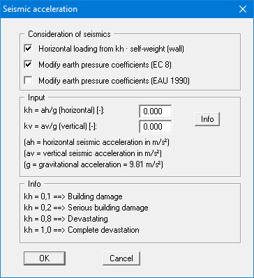
"Seismic acceleration" menu item
Seismic loads are given in multiples of gravitational acceleration. The following options, which can be selected individually or together, are available for taking seismic loads into consideration:
The self-weight of the wall or equivalent wall is multiplied by the seismic acceleration factor and taken into consideration as additional horizontal loads in the analysis.
Seismic loads are taken into consideration as described in EC 7 or EAU 1990, section 2.14, by increasing the active earth pressure coefficients and reducing the passive earth pressure coefficients.