
"Graphic preferences" menu item
If you are analysing a gabion wall with geogrids you can define preferences for the visualisation here.
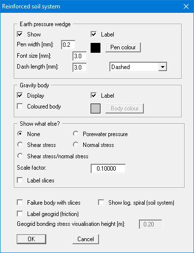
The earth pressure wedge and gravity body are explained in section 7.21.2. The visualisation of these elements can be influenced in the two upper group boxes of this dialog box.
In the "Show what else?" group box you define whether the visualisation of the two-part wedge failure mechanism with the lowest factor of safety should include additional information (e.g. the shear stress). The values for each slip body slice are shown perpendicular to the slip surface. The scale is given using the input field for the "Scale factor".
The failure body can be visualised together with slices. Moreover, the logarithmic spiral (bearing capacity) of the reinforced soil system can be shown. The geogrid bonding stresses are automatically calculated from the surcharges. These can also be visualised. The visualisation height can be entered in the input box at the bottom.
"Verifications" menu item
Using this menu item you can specify the entries made in the legend and the output table.
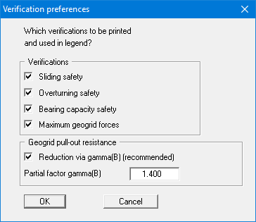
For example, if you do not want to calculate the bearing capacity safety, you can turn off the bearing capacity verification.
"Enter geogrids manually" menu item
Define the position and material properties of geogrids using this menu item. The defined geogrids are displayed after closing the dialog box.
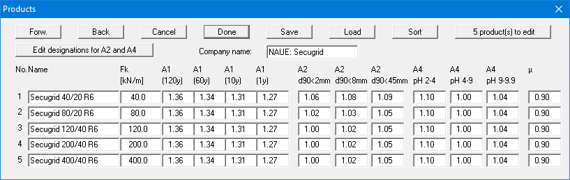
When using geogrids, it is possible to directly adopt certain products of various geogrid manufacturers. When the program starts the "File/New" or "Editor 1/Analysis options" dialog box therefore has the "Geogrids via company products" check box activated (see section 8.1.1). A dialog box will open, where the number of geogrids must be defined using the "0 Geogrids" button.
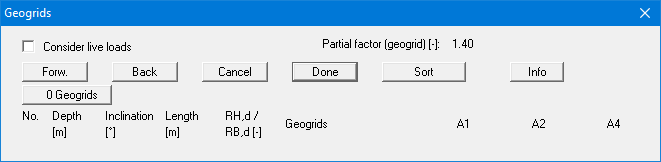
The required company product can then be selected for each of the geogrids. The coefficients defined for a geogrid, the length and the inclination can be adopted for the remaining geogrids by using the "For others" button.
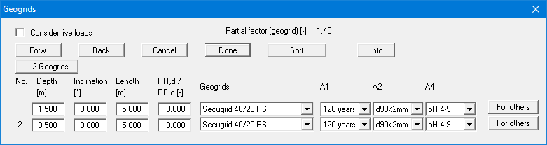
A maximum of 8 geogrids are shown in the list. You can navigate through the list using the "Forw." and "Back" buttons. Using the "Sort" button, you can sort the geogrids according to depth. For example, if you wish to delete the top geogrid from the table simply assign a very small depth (e.g. "-100") and press "Sort". The geogrid has now moved to the lowest position in the table. Now reduce the number of geogrids by 1.
If geogrids by a different manufacturer are required, go to the menu item "Editor 1/Geogrids table values". Here, products by different manufacturers can be selected (see section 8.4.10).
If you do not work with company products, the following dialog box opens:
Where:
RB,d = design resistance of geogrid;
RH,d = design resistance of geogrid at junction (generally = 0.8 · RB,d).
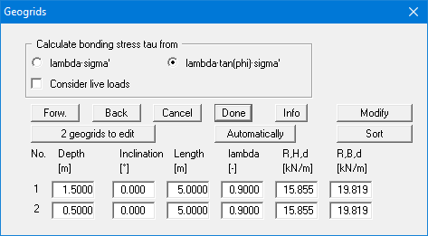
The bonding stress tau is automatically calculated by the program. Define the subsequent actions in the upper group box of the dialog box. Usual practice is to calculate the bonding stress tau from the effective stress (sigma') and the tangent of the friction angle phi and then to reduce this value by lambda. The alternative to this is to calculate the bonding stress from a multiplication of the effective stress and a friction coefficient. In this case lambda no longer represents a reduction factor, but instead a friction coefficient.
If you would rather define the geogrid yourself, click on the "x geogrids to edit" button and then enter the required number of geogrids. A maximum of 8 geogrids are shown in the list. You can navigate through the list using the "Forw." and "Back" buttons.
Using the "Modify" button it is possible to simultaneously assign all geogrids certain values or to change the values entered. This function is available by going to the "Reinforced soil system/Modify geogrids" menu item (see section 8.4.5).
The "Automatically" button allows you to generate a completely new geogrid system. This function is also available by going to the "Reinforced soil system/Generate geogrids" menu item (see section 8.4.4).
"Generate geogrids" menu item
You can generate a completely new geogrid system using this menu item. Activate the "Delete existing geogrids" check box. If this check box is not activated, you can add further geogrids to the previously existing ones.
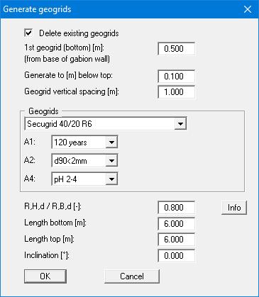
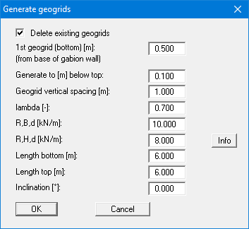
If you do not work with company products, the dialog box for this menu item corresponds to the dialog box displayed when you press the "Automatically" button in the "Reinforced soil system/Enter geogrids manually" menu item.
"Modify geogrids" menu item
Using this menu item, you can edit the data for all geogrids simultaneously in a single step. Enter a value and start the modification using the respective "Apply" button following the desired action. Only this action is subsequently performed.
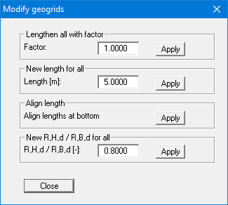
If you do not work with company products, the dialog box for this menu item corresponds to the dialog box displayed when you press the "Modify" button in the "Reinforced soil system/Enter geogrids manually" menu item.
"Generate slip surfaces" menu item
Using this menu item, you can generate a large number of slip surfaces for the two-part wedge failure mechanism with just a few details.
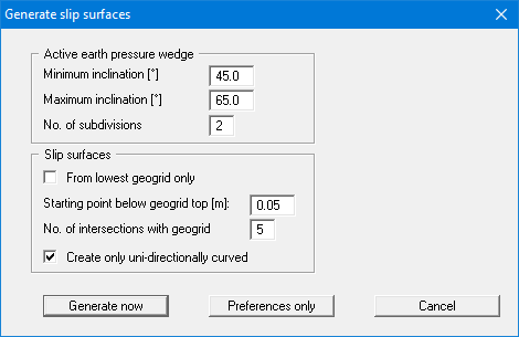
The two-part wedge failure mechanism contains a slip surface in the right area, which correspond to the active earth pressure wedge. According to theory this earth pressure wedge has an inclination of 45° + /2 (see section 7.21.2). Values smaller than 45° are thus not possible. Values greater than 65° only result if the angle of friction of the soil is greater than 40°. The default values in the dialog box therefore cover the usual construction range. The input for "No. of subdivisions" indicates the number of intermediate angles to be generated between the two limiting angles.
In the lower group box, it is possible to influence the left side of the two-part wedge failure mechanism. If you activate the "From lowest geogrid only" check box (not recommended), only failure mechanisms with bending points on the lowest geogrid are generated. The "Starting point below geogrid top" value defines the left-hand point of the failure mechanism. The input for "No. of intersections with geogrid" defines the number of central points of the failure mechanism.
The effects of the individual inputs are difficult to describe in words. So just try editing the input in the dialog box and then click "Generate now". You will see immediately the failure mechanisms generated by the program in the graphics. If you close the dialog box using the "Preferences only" button, the current analysis results will not be affected. However, when you start a new analysis that includes geogrids these settings will be used to generate the appropriate failure mechanisms.
"Geogrid forces" menu item
During analysis of the defined failure mechanisms the program calculates the maximum geogrid forces and divides these by the safety factor of the respective failure mechanism. Using this menu item, you can view the maximum geogrid forces for each geogrid layer.
"Sliding, overturning, bearing capacity" menu item
Verification is in accordance with the notes in the "Theoretical principles" section. You will see the results in dialog boxes.
"Calculate earth pressure + weight" menu item
You can calculate earth pressure and weight independent of previous menu items. The results are shown in message boxes.
"Geogrids table values" menu item
The geogrids of various manufacturers can be imported and supplemented using this menu item. Editing the data is not recommended! In general, in GGU-GABION importable files can be requested from the geogrid manufacturers. Data files from various manufacturers are installed in the program folder when the program is installed.
Other manufacturer's products can be imported using the "Load" button. When importing it is possible to specify whether to import the products of only one manufacturer or the products of several manufacturers together in one list. If you store your geogrids list in a "GGU-GABION.ggu_geo" file on the program level, the product list is automatically imported when the program is started.
In order to be able to select the geogrid products, the "Geogrids via company products" check box must be activated in the menu item "File/New" or "Editor 1/Analysis options" (see section 8.1.1). We also recommend activating the "Store company products in record" check box. Otherwise, if the file is opened on a computer that does not have the ".ggu-geo" files installed, the originally selected products are deleted.
The geogrid products can be selected in the menu item "Reinforced soil system/Enter geogrids manually" or "Reinforced soil system/Generate geogrids".