
Berms
GGU-GABION can handle berms on both the active and the passive sides of the wall. The berms may include surcharges. The effect on earth pressure is taken into consideration according to the Piling Handbook (Krupp Hoesch Stahl).
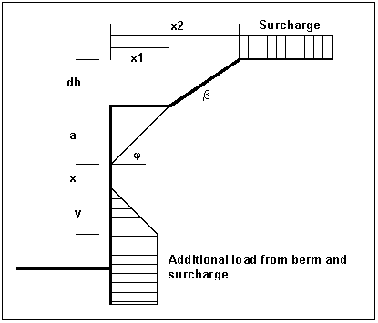
Figure 4 Berm on the active side
The following relationships apply for the parameters x and y:
x = kah0 / (kah - kah0) · a
y = kah0 / (kah - kah0) · x
eahu = · dh + surcharge
= unit weight of soil in the berm area
If the angle is greater than , it is assumed that = for analysis. Berms on the passive side are dealt with in the same manner.
Area loads
Up to 20 area loads can be positioned on the active side at any height.

Figure 5 Area load
The slip surface angle for the active earth pressure resulting from the self-weight of the soil is adopted for analysis compliant to DIN 4085.

When there are several soil layers, GGU-GABION moves from layer to layer applying the appropriate angles of friction. The type of the resulting earth pressure distribution can be specified in 4 different ways.
For at-rest earth pressure, the area loads are calculated by increasing by the factor k0/kah in compliance with DIN 4085:2011 section 6.4.3.
Alternatively, it is possible to determine the demands placed on a wall from area loads using the theory of elastic half-space. The two load concentration factors '3' and '4' can be taken into consideration (see also Figure 6).
For over consolidated, cohesive soils the concentration factor '3' applies, where:
eop = q/ (2 - 1 + cos1 sin2 - cos2 sin2)
For non-cohesive soils, or for cohesive but not over consolidated soils, the concentration factor '4' applies, where:
eop = q/4 (sin³2 - sin³1)
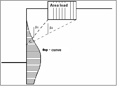
Figure 6 At-rest earth pressure from area loads
With regard to the kind of earth pressure, area loads can be defined independent of the global preferences (see menu item "Editor 1/Type of earth pressure", section 8.2.9).
Loads with limited plan dimensions
Loads with limited plan dimensions can be reduced compliant with "Piling Handbook" Figure 4.20 (page 64) or DIN 4085:2017-08 (page 17), see also Section 8.3.1.
Bounded surcharges (active side)
Up to 40 bounded surcharges can be positioned at any height on the active side.

Figure 7 Bounded surcharge (active side)
The earth pressure coefficient k is acquired from kah for active earth pressure and from k0 for at-rest earth pressure. If this option is activated, the resulting earth pressure is then redistributed.
If negative values are entered, e.g. in order to generate a double-bounded surcharge, the linear component between and may not be adopted.
Double-bounded surcharges (active side)
If two bounded surcharges are defined as follows:

Figure 8 Two bounded surcharges
Bounded surcharge 1:
begins at x = 1,00 m and has the value p.
Bounded surcharge 2:
begins at x = 2,00 m and has the same value as surcharge 1 but with a negative sign
(see the explanation on the previous page, section 7.9).
A double-bounded surcharge, which acts as a consequence of p at x = 1.00 to x = 2.00, is thus defined as the result of earth pressure analysis. However, the graphics are not really satisfactory and may be irritating for an examiner. Double-bounded surcharges were therefore introduced.

Figure 9 Double-bounded surcharge
The same result is achieved as for the definition provided by Figure 8 but with improved graphics.
The area loads described in section 7.8 are based on different assumptions for the resulting earth pressure, so the definition of a double-bounded surcharge does not provide the same result as an equivalent area load.
Bounded surcharges (passive side)
Up to 40 bounded surcharges may be adopted at any height on the passive side. The passive earth pressure is computed as follows:

Figure 10 Bounded surcharge (passive side)
Double-bounded surcharges (passive side)
Double-bounded surcharges on the passive side can be modelled using two bounded surcharges (also see section 7.11). Double-bounded surcharges on the passive side were only implemented due to the better graphical representation.
Structural system
The structural analysis required to determine the state variables (displacement, moment, shear force and normal force) is by means of a rod construction module, which treats the wall and any geogrids as a single structural system. The wall is taken into consideration as a rod construction, running along the centroid of the wall.

Figure 11 Structural system of a wall without geogrid
The stiffness EI of the wall is acquired from E·d³/12, where d is the horizontal thickness of the wall in the section under consideration. The stiffness of each element is assumed as constant, where the thickness is the thickness at the centre of the section.
If geogrids exist in the system, the point of acting is automatically placed in the centroid axis. The force components acting on the front and rear of the wall, such as soil weight, water pressure, loads, etc. produce a moment around the centroid axis, which GGU-GABION takes into consideration as a continuously distributed moment load on the rod axis.
The theoretical principles of the rod construction module can be traced back to an article by Duddeck/Ahrens (Betonkalender 1976 (Concrete Calendar), Volume 2). Basically, this is a finite element method based on the displacement method. The division of the wall and the struts into rod sections (finite elements) can be controlled by input (see "System/Depth subdivisions" menu item in section 8.5.3).
Using FEM produces equation systems in which the number of unknowns is a function of the number of rods. The solution to the equation system is acquired in GGU-GABION using Cholesky's method, which is also employed in other GGU programs and is numerically highly stable. Nor have there been any numerical difficulties reported from other GGU applications.
Amongst the results of the rod construction analysis are the shear forces Q and the normal forces N regarding the rod axis. In a post-processing calculation these forces are converted to the horizontal force H and the vertical force V.
Base inclination
Base inclination is generally carried out to increase the sliding safety to the required level.

Figure 12 Base inclination
The idealisation of the body without base inclination to an equivalent structural system (elastic curve) presents no problems, because the stiffness of the individual partial calculations can be calculated from the horizontal thickness. However, the wedge-shaped extension that normally occurs with base inclination is contradictory to the demands which arise when the wall is analysed as an elastic curve.
In order to disqualify contradictory results from the outset, the base inclination is not taken into consideration when determining the action effects. Only when verifying the safety against sliding are the active and passive earth pressures at the left and right of the wedge cumulated and this component allocated to the horizontal force when verifying the safety against sliding. When verifying the bearing capacity safety (see section 7.22.1), base inclination is taken into consideration. The additional horizontal force component is not incorporated in the analysis, leading to a more conservative result.
Bedding conditions of wall toe
For systems without geogrids the wall toe is fully fixed. In systems using geogrids, the wall toe can either be defined as fixed, freely pivoted or with an embedded base.
Action and displacement boundary conditions
GGU-GABION automatically sets the boundary conditions described in section 7.14 (Structural system). It is also possible to enter additional boundary conditions for any point on the wall. All six state variables can be defined as boundary conditions:
displacement along x-axis,
displacement along y-axis,
rotation,
horizontal force,
vertical force,
moment.
Earth pressure redistribution
According to EBGEO, there is no requirement for redistribution of earth pressure. It is nevertheless possible to select from a large variety of redistribution figures. In addition, by defining a polygon, the user can create any redistribution figure. The figures available are given below:
Rectangle,
2 rectangles,
triangle, maximum at top,
triangle, maximum at centre,
triangle, maximum at base,
trapezoid,
rectangle with maximum at anchor locations or at any point,
user-defined redistribution figure by means of a polygon
EAB redistribution figures.
GGU-GABION gives you the option of including or excluding area loads in the redistribution.
Verification concept
Verifications
When you begin an analysis, the program requires the stiffnesses of the wall. The stiffness EI of the wall is acquired from E·d³/12, where d is the thickness of the wall in the section under consideration. The stiffness of each element is assumed as constant, where the thickness is the thickness at the centre of the section.
Once the structural analysis is complete the program performs the necessary verifications. If any verifications are not possible you will see an appropriate warning. The following verifications can be differentiated:
verification of internal stability,
verification of external stability,
verification of serviceability limit state.
These are further differentiated:
systems without reinforcement (geogrid) and
systems with reinforcement (geogrid).
If, for whatever reason, you would sooner do without any of the verifications listed here, go to the "Editor 1/Verifications/Safety factors" menu item or the "Editor 1/Verifications/Partial factors" menu item and select the required verifications. The settlement analysis can be activated or deactivated by going to "Editor 2/Settlements".
Systems without geogrids
External stability
The following verifications must be performed:
Sliding safety in the base plane (EC 7/DIN 1054):
The verification is performed using the soil properties at the base plane
(see section 7.20.1).
Bearing capacity safety (DIN 4017):
The verification is performed using the soil properties below the base plane
(see section 7.22.1).
General stability (DIN 4084):
This verification can be performed using the GGU-STABILITY program after exporting the data (see "File/Export" menu item, section 8.1.6).
Internal stability
The internal stability analysis must verify that no material incompatibilities or overloading arises within the gabion wall. The following verifications must be performed:
Sliding safety in horizontal joints (EC 7/DIN 1054, see section 7.20.2),
Verification of gabions (EC 2/DIN 1045, see section 7.25.2, or DIN 4093, section 7.25.3).
Serviceability
The verifications of serviceability consist of:
Verification of allowable eccentricity of the resultant in the base plane,
Settlement considerations based on DIN 4019 (see section 7.23).
Systems with geogrids
Systems with geogrids are considered as reinforced soil systems with a retaining gabion wall.

Figure 13 Wall with geogrid
Verification of the overall reinforced soil systems is based on section 6.7 of the Recommendations for Reinforcements using Geosynthetics (Empfehlungen für Bewehrungen aus Geokunststoffen - EBGEO). This requires the following verifications for the reinforced soil system:
Verification of the bearing capacity of reinforced soil systems
Sliding safety verification (see also section 7.21.2),
Bearing capacity safety verification (see also section 7.22.1),
General stability verification (see also section 8.1.6),
Verification of the bonding of the reinforcement with the gabion wall,
Verification of internal stability of the reinforced soil system (see section 7.21.1).
Verification of the serviceability of reinforced soil systems
Verification of allowable eccentricity of the resultant in the base plane of the reinforced soil system,
Reinforced soil system settlement considerations based on DIN 4019 (see section 7.23).
Because the gabion wall can be of considerable thickness, in contrast to those systems dealt with in the EBGEO, and because they may also possess a strip footing, bearing capacity and serviceability verifications are also required:
External stability (bearing capacity) of the gabion wall
Sliding safety in the base plane (EC 7/DIN 1054, see section 7.20.1),
Bearing capacity safety (DIN 4017, see section 7.22.1).
Internal stability (bearing capacity) of the gabion wall
Sliding safety in horizontal joints (EC 7/DIN 1054, see section 7.20.2),
Verification of gabions (if necessary, to EC 2/DIN 1045-1, see section 7.25.2),
Verification of the bonding of the reinforcement with the gabion wall.
Verification of the serviceability of the gabion wall
Verification of allowable eccentricity of the resultant in the base plane,
Settlement considerations based on DIN 4019 (see section 7.23).
Sliding safety to EC 7
Sliding safety in the base plane
The sliding safety is calculated using:
= Vk · tan / Hd
Vk = characteristic vertical force
Hd = design value of horizontal force
The friction angle is obtained from the mean of the soils in the base plane of the wall.
Sliding safety in the horizontal joints
Enter a friction coefficient for verification of the sliding safety in the horizontal joints in the dialog box that opens in the "Editor 1/Body (general)" menu item :
The program calculates the sliding safety using:
Friction coefficient · Vk / Hd
for all horizontal sections.
Verifications reinforced soil system
Internal stability
Verification of the internal stability of the reinforced soil system is regulated in EBGEO. Verification uses the methods described in DIN 4084. The program assumes a failure system consisting of two slip planes (two-part wedge failure mechanism).
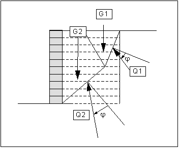
Figure 14 Two-part wedge failure mechanism
If one or more layers of reinforcement are intersected by this failure mechanism, the maximum force in a reinforcement layer must be determined according to EBGEO, this involves examination of whether:
the design resistance RB,d of the reinforcement layer is exceeded or,
the pull-out to the "left" or "right" of the slip surface is governing (RA,d).
The design resistance RB,d of a geogrid according to EBGEO (section 6.1.3) is determined using:
RB,d = RB,k0 / (A1 · A2 · A3 · A4 · A5) / M
RB,k0 = characteristic value of the short-term strength
M = partial safety factor for the material resistance of the geogrid
(in Load Case 1 to DIN 1054 = 1,40)
A1 = creep strain or creep rupture reduction factor
A2 = transport, installation and compaction reduction factor
A3 = connections reduction factor
A4 = environmental influence reduction factor
A5 = dynamic actions reduction factor
The following comparisons need to be considered when calculating the maximum design value of the pull-out resistance RA,d RA,d:
The maximum pull-out resistance within the slip body ("left") RA1,d is acquired from the force RH,d with which the geogrid is attached to the gabion wall and the bonding stress A1,d that can be activated within the slip body.
According to EBGEO a value of
RH,d = 0,8 · RB,d
can be adopted for RH,d.

RA1,d = RH,d + 2 · L1 · A1,d
The maximum pull-out resistance RA2,d outside of the slip body ("right") is acquired from the bonding stress A2,d behind the slip body.
RA2,d = 2 · L2 · A2,d
In accordance with EBGEO the bonding stress A,d is acquired from:
A,d = fA,k · V,k / B = k · tan k · V,k / B
fA,k = characteristic friction coefficient between geosynthetic and fill
k = characteristic ratio of friction angle between geosynthetic and fill
k = characteristic angle of internal friction of fill
V,k = characteristic normal stress due to reinforcement layer surcharge
B = partial safety factor for the pull-out resistance of the reinforcement
(in Load Case 1 to DIN 1054 = 1,4)
The minimum values of RA1,d , RA2,d and RB,d are governing for stability analyses to DIN 4084.
The analysis of the structural system as a frame system results in support forces in a system using geogrids (tension forces in the geogrids). It is therefore also necessary to subsequently verify that the maximum acceptable force in the geogrids is greater than the calculated support force.
External stability
To verify the external stability of the reinforced soil system the weights and horizontal earth pressures, amongst other things, acting on the soil body must be calculated. This is done on equivalent systems. The data in Figure 15 can be used for the weight calculation.

for x
for y
2nd point for rear face
≤ 45 + /2
Figure 15 Equivalent system for weight calculation
The weight of the hatched area is determined. The lower right point of the system is given by the x-value of the lowest end of the geogrid and the y-value of the base of the gabion wall. The rear face corresponds to a line connecting this point to the end of the upper geogrid (irrespective of the length of any intervening geogrids). The inclination of the rear face of the wall cannot become steeper than the inclination of the active earth pressure wedge (see further below).
The horizontal loading is given by the active earth pressure. The vertical section for which the earth pressure is determined is represented in Figure 16.
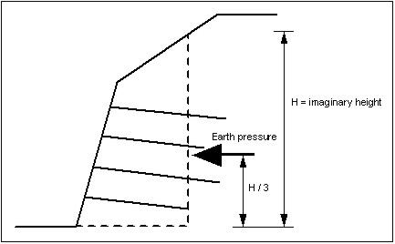
Figure 16 Vertical section for earth pressure determination
Calculation of earth pressure is by means of a variation of the rearward earth pressure wedge. In order to take into consideration any inclination of the rear face of the wall a reduction is carried out via the earth pressure coefficients kah for both a vertical rear face ( = 0) and an inclined rear face ( ≠ 0), after determining the earth pressure:
Reduction factor (earth pressure) = kah()/kah( = 0)
Sliding safety G is calculated from:
G = Gk · tan /Hd
Gk = characteristic weight
Hd = design value of horizontal force
The friction angle is obtained from the mean of the soils in the base of the reinforced soil system.
Overturning safety
Using the information provided in section 7.21.2 "Verifications of reinforced soil system/External stability" the moment and the vertical force in the base plane are calculated and the eccentricity e determined from the result. The moment resulting from the horizontal earth pressure is determined according to Figure 16 (Vertical section for earth pressure determination) in the section above. For example, the eccentricity in Load case 1 may not be greater than b/6.
Distribution of earth pressure on the gabion wall
Knowledge of the earth pressure distribution on the gabion wall is of critical importance for the verifications listed above. The factor fq may be reduced based on the EBGEO.
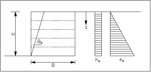
Figure 17 Slip surface and earth pressure distribution
The load q acting on the gabion wall q is calculated from:
q = fq · k · · z
fq = 0.8 for B/H 0.7 and fq = 1.0 for B/H 0.5
(linear interpolation between)
k = earth pressure coefficient according to Figure 17
= unit weight of fill
z = ordinate
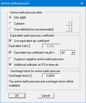
The reduction factor fq can be entered using the menu item "Editor 1/Active earth pressure". In a system using geogrids the program checks that the ratio H/B and, where necessary, informs either that a reduction in earth pressure is possible or that the earth pressure reduction used is too large.
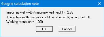
If you close this dialog box using "OK", the program proceeds to calculate with the values provided. However, if you use the "Cancel" button, a query will appear asking if the allowable value determined in accordance with the above stipulations should be used. If you confirm this with "Yes" the program accepts this value for the reduction without you having to go to the menu item "Editor 1/Active earth pressure".
Bearing capacity safety
Analysis principles
The bearing capacity analysis will be carried out according to DIN 4017:2006. The following relationship applies:
0f,k = c · Nc + 1 · d · Nd + 2 · b' · Nb
Additionally, the depth coefficients Tc and Td not documented in DIN 4107 may be taken into consideration.
0f,k = characteristic bearing stress
c = cohesion [kN/m²]
Nc = bearing capacity coefficient cohesion
1 = unit weight of soil above footing base
d = embedment depth of footing
Nd = bearing capacity coefficient footing depth
2 = unit weight of soil below footing base
b' = calculated depth of footing
Nb = bearing capacity coefficient footing width
Bearing capacity coefficients Nc, Nd and Nb
Nc = Nc0 · c · ic · c · c · Tc
Nd = Nd0 · d · id · d · d · Td
Nb = Nb0 · b · ib · b · b
The following values are adopted:
Nc0 Nd0 Nb0 according to DIN 4017
c d b according to DIN 4017 (shape coefficients)
When entering the system data input of a length is principally of importance for the calculation of settlement. The program consistently uses the values for a and b, including for calculation of the shape coefficients d and b for strip footings, as this delivers somewhat more favourable values.
d = 1 + 00.2 · b/a (instead of 1.0 for strip footings)
b = 1 + b/a · sin() (instead of 1.0 for strip footings)
ic id ib according to DIN 4017 (load inclination coefficients)
c d b according to DIN 4017 (ground inclination coefficient)
c d b according to DIN 4017 (base inclination coefficients)
Tc Td = depth coefficients according to the Danish standard (not permitted to DIN 4017)
Tc = Td = 1 + 0.35 · GS / b 2.0
GS = footing base
b = footing width
Determining the mean governing soil properties
DIN 4017 instructs that the mean soil properties of the soil above the bearing capacity failure plane, which is composed of the two linear components of a logarithmic spiral, can be determined for stratified ground. The governing parameters are summarised in the figure:

Figure 18 Logarithmic spiral
The mean governing soil properties are determined using the following relationships:
cal tan = tan i · li’ / li
cal c= ci · li’ / li
cal 2 = 2i · Ai’ / Ai
li = length within individual layer
Ai = area of individual layer
The condition for the permissibility of the mean is that the mean friction angle demonstrates a maximum deviation of 5° to the true friction angles. This condition can be checked by the program. If it is not adhered to, the program reduces the largest friction angle in stages until the condition is met.
Settlements
Analysis of settlement is compliant with DIN 4019 using the relationships given in the Geotechnical Engineering Handbook (1990; Fourth Edition) (equations 8 and 14 from section 1.7 Stress analyses). The program determines the stresses at 0.05 m intervals or at layer boundaries and numerically integrates them.
The limiting depth can be defined in three different ways:
with a fixed, user-defined value,
as a multiple of the footing width,
as the depth at which the total vertical stress exceeds the overburden stress by x%
(generally 20%).
If the base of the lowest layer is exceeded during the settlement analysis, the analysis continues using the constrained modulus of this final layer.
For settlement analyses, any preconsolidation loading in kN/m² can be subtracted from the current soil pressure. Settlement analysis will then be performed with the reduced values. The overburden pressure is also reduced by this amount when calculating the limiting depth.
General stability
The general stability (see EAB, R 10, Para. 3) can be simply verified by exporting the data from GGU-GABION to GGU-STABILITY (GGU slope stability application).
Analysis of internal stability
Analysis to DIN 1045 (old)
The following data are required for internal stability analysis:
beta(r)
designates the nominal strength of the material (see also DIN 1045).
n-value
DIN 1045 states that a load distribution may be taken into consideration up to an inclination of 1:2 to the direction of the load. Depending on the soil pressure, other n-values can also be used (see DIN 1045; Table 17 for information on this). Together with the load transmission width, this allows calculation of the width to be adopted for the complete height when verifying internal stability.

Figure 19 n-value and width for internal stability analysis
Internal stability analysis is performed using the following relationship to DIN 1045:
allow. N = · 1 / 2.1 · b · beta(r) · (1.0 - 2 · e) [kN/m]
b = governing width of concrete
e = eccentricity with regard to governing width
= reduction for slenderness of structural element
is a coefficient for considering the slenderness and unintentional eccentricity to DIN 1045 (Equation 20). is calculated from:
= 1 - /140 · (1 - m/3)
m = e/k (e = M/V and k = b/6)
= slenderness (for rectangular sections = sk/b · 12)
sk = buckling length
The buckling length sk in systems without geogrids is given approximately by twice the separation between the top of the wall and half of the embedment depth. For walls that are horizontally restrained near the top by other engineering elements, the single separation may be adopted. The horizontal restraint can be specified using the "Wall top kept horizontal" check box. In systems which include geogrids, sk is acquired from twice (once) the separation between the top of the walland the upper geogrid layer, or the separation between the individual geogrid layers. The slenderness is recalculated for every section using the respective governing gabion width. The program deals with the appropriate selections except for the "Wall top kept horizontal" setting.
The allowable N calculated in this manner is compared to the existing normal force working N. The utilisation factor g is then acquired from the relationship:
g = working N/allowable N.
Internal stability analysis can also be performed using a partial section.
Analysis to EC 2/DIN 1045-1
The internal stability of the gabion structure can be analysed for unreinforced concrete in all governing horizontal sections using the following relationship based on EC 2/DIN 1045-1:
NR,d = b · fm,d ·
= 1,14 · (1 – 2 ·etot/b) - 0.02 sk/b
(0 ≤ ≤ 1 – 2 · etot /b)
NR,d= design value of the acceptable longitudinal force
b = width of body in respective section
fm,d = equivalent design value of concrete compressive strength
e = eccentricity in respective section
etot = total eccentricity = e0 + ea + e
e0 = load eccentricity according to first order theory
ea = additional unintentional eccentricity as a result of geometric imperfections
(If more precise data is not available, ea may be assumed at = 0.5 l0/200.)
eφ = eccentricity resulting from creep (can be disregarded for gabions)
sk = buckling length
The buckling length sk is given approximately by twice the distance between the top of the wall and half of the embedment depth.
The equivalent design value of the concrete compressive strength fm,d is determined from load tests performed on a gabion basket.
The design value of the acceptable longitudinal compressive force NR,d and the design value of the acting longitudinal compressive force NE,d are determined in every governing section. The following condition must be adhered to:
NR,d ≥ NE,d
Analysis to DIN 4093
Ultimate limit state
The analysis of sufficient gabion strength is performed compliant with DIN 4093:2012-08 (Design of strengthened soil). The design value of the compressive strength of the gabion fm,d required for this purpose is derived from load tests.
DIN 4093:2012-08 stipulates that, in approximation, separate analyses may be performed during design for the acceptable compressive and shear stresses. Under design loads it must be demonstrated that the design values of the normal stresses σE,d do not exceed 0.7 · fm,d and the design values of the shear stresses τE,d do not exceed 0.2 · fm,d.
The normal stresses σE,d are determined assuming a linear distribution.
σE,d = ME,d/W + NE,d/A ≤ 0.7 · fm,d (no foundation gap)
ME,d = design value of the moment
W = section modulus
NE,d = design value of normal force
A = cross-sectional area
σE,d = 4 · NE,d/(3 · b – 6 · e) ≤ 0.7 · fm,d (foundation gap)
NE,d = design value of normal force
b = width of cross-section
e = eccentricity
If analysis results in a foundation gap, the area of the gap may not be adopted in an analysis of the shear stresses.
The design value of the shear stress τE,d is given by:
τE,d = 1.5 · QE,d/Av ≤ 0.2 · fm,d
QE,d = design value of the shear force
Av = cross-sectional area under shear loading
The characteristic value of the compressive strength of the gabion fm,k is determined from load tests. The corresponding design value of the compressive strength fm,d is given by:
fm,d = α · fm,k/γm
α = coefficient for considering a long-term effect = 0.85
γm = partial safety factor for the compressive strength
(= 1.5 for DS-P and DS-T
= 1.3 for DS-A)
Serviceability limit state
In load tests on gabions, the failure stress is often only reached with large deformations. The stress σE,k,SLS (SLS = serviceability limit state) at which the deformation of the gabion reaches the value allowable for the serviceability analysis is determined from the stress-deformation curve. The following analysis must then be performed:
σE,k = ME,k/W + NE,k/A ≤ σE,k,SLS (no foundation gap)
ME,k = characteristic value of the moment
W = section modulus
NE,k = characteristic value of normal force
A = cross-sectional area
σE,k = 4 · NE,k/(3 · b – 6 · e) ≤ σE,k,SLS (foundation gap)
NE,k = characteristic value of the normal force
b = width of cross-section
e = eccentricity
This serviceability analysis can also be selected for analysis compliant with EC 2, which we recommend (see "Editor 1/Analysis options"/"File/New" dialog boxes, section 8.1.1).
Slenderness
DIN 4093:2012-08 stipulates that when analysing the ultimate limit state the slenderness λ ≤ 15,
if no buckling safety analysis is performed. This can not always be demonstrated. However, the normal force loading on gabion walls is generally insignificant, and the analysis concepts in EN 1993-1-1:2010-12 are helpful. EN 1993-1-1:2010-12 states that buckling safety analysis may be dispensed with if the following condition is adhered to:
NEd/Ncr ≤ 0.04
NEd = design value of the normal force
Ncr = ideal bifurcation load for the governing buckling case
Ncr = E·I · π²/sk²
E = Young’s modulus of the gabion
I = moment of inertia
sk = buckling length
According to expert opinion, the criterion to EN 1993-1-1:2010-12, Para. 6.3.1.2 (4), where NEd/Ncr ≤ 0.04, is a ridiculously strict criterion and will be dispensed with in future standards. In future the tried and tested rule in Para. 5.2.1 applies, Eq. (5.1): NEd/Ncr ≤ 0.1.
The investigation may therefore be performed using
NEd/Ncr ≤ 0.10.