
After selecting this menu item a dialog box appears, in which you can edit preferences for graphical presentation.
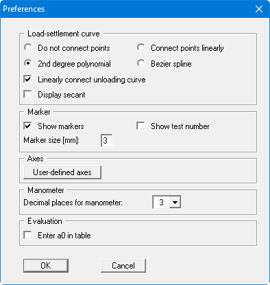
By activating the "Do not connect points" switch, you can ensure that the measured values are not connected to a load-settlement curve. Only in rare cases, e.g. if you need to draw a load-settlement curve by hand, you will use this switch.
According to DIN 18 134, a 2nd degree polynomial using compensation according to the least squares method is required for analysis of the plate loading test. This method is utilised in all cases to determine the governing plate loading values, completely independently of the smoothing out procedure selected here. However, representation of the plate loading test using the "2nd degree polynomial" switch sometimes leads to rather unusual curves. Alternatively, then, and for optical effect only, you can select between the methods "Connect points linearly" or "Bezier spline" for the representation.
Regardless of the selected setting for the load-settlement curve you can separately specify a linear connection for the unloading curve data points. In addition it is possible to display the secant in accordance with Figure 4 of DIN 18134.
By activating the "Show markers" or the "Show test numbers" switch the load-settlement curve will be displayed with markers or their current numbers at all measuring points. You can switch off both, when you only want to display the curve on the output sheet. The size of the markers can be influenced with the input in the "Marker size [mm]:" field.
Using the "User-defined axes" button it is possible to define your own axes scales. Otherwise, the axes will be scaled automatically. If you select this button you are first offered the automatic scale values in a box, which you can then edit as required.
In addition, you can vary the number of decimal places for manometer data input between "3" and "5" for each plate loading test performed.
The value a0 should be given in the evaluation of your plate loading test in compliance with DIN 18134. Display in the "Deformation modulus" evaluation table can be achieved by activating the check box "Enter a0 in table".
When you leave the dialog box with "OK", all preferences will be accepted.