
System description
Knowing from experience that having to work one's way through a software manual can be very tiresome, the following sections provides a short description of GGU-RETAIN's main functions, which will quickly enable you to carry out a retaining wall analysis. Details, when needed, will be found in the appropriate chapter of this manual. The following example of a retaining wall is to be analysed:
Figure 1 Illustration of worked example 1
The example is a soldier pile wall with an anchor at the top of the wall. The groundwater level coincides with the excavation base. On the active side there is a berm, subjected to a load of 10 kN/m². The soldier pile centres are 2.2 m. "HEB 300" soldier piles are to be used and analysed with a free earth support.
Step 1: Select analysis options
After starting the program, the logo is displayed. Select the menu item "File/New". The following dialog box will appear:
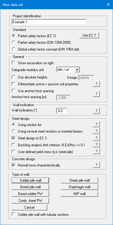
Select the buttons shown in the above dialog box and click "Soldier pile wall". A new system is displayed on the screen and the complete menu bar is activated.
Step 2: Define excavation and retaining wall
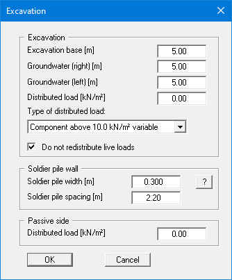
From the "Editor 1" menu select "Excavation". The following dialog box will appear. Enter the figures shown below:
Step 3: Define berm
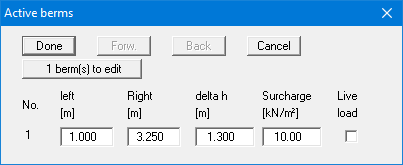
Go to the "Editor 1" menu and select "Berms (active side)":
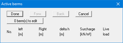
Click "0 berm(s) to edit" and enter 1 as the new number of berms. Enter the following values and click "Done".
Step 4: Define soils
Go to the "Editor 1" menu and select "Soils".
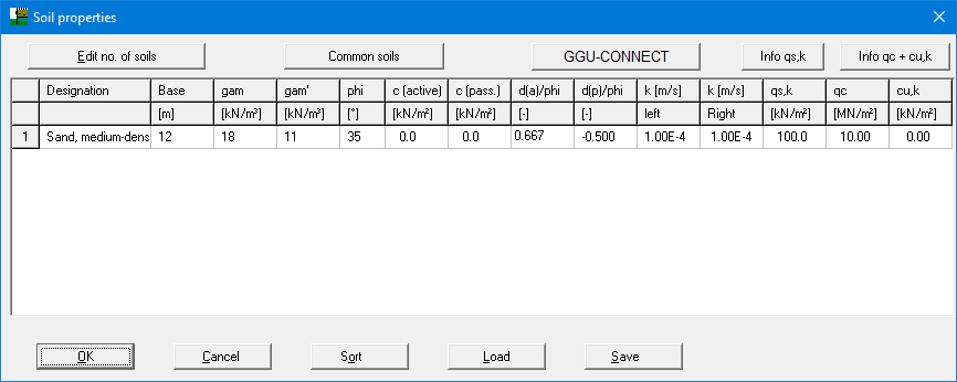
Enter the values shown in the above dialog box.
Step 5: Define type of earth pressure
Go to the "Editor 1" menu and select "Type of earth pressure".
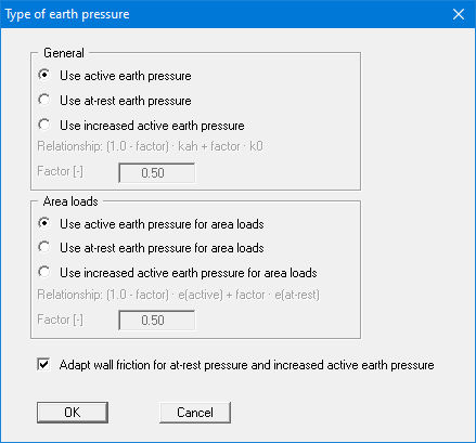
The necessary command buttons are already selected, so you need not change anything. The same applies to the remaining menu items in "Editor 1". However, you should click on these items and look at them, to familiarise yourself with them.
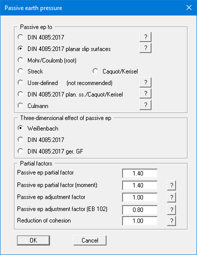
Step 6: Define passive earth pressure
Go to the "Editor 1" menu and select "Passive earth pressure" and accept the default setting.
Step 7: Define anchors
Go to the "Editor 2" menu and select "Anchors". Now click "0 anchor(s) to edit" and set the number to 1.
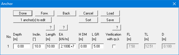
Enter the values shown in the above dialog box. Click "Done" and you have completed data entry.
Step 8: Analyse and design the system
Go to the "System" menu and select "Analyse".
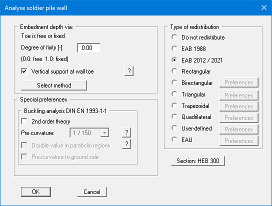
Select a degree of fixity of "0.0" (= free earth support). Earth pressure redistribution is in accordance with the EAB 2012/2021 (activate the appropriate command button). The required section can be selected using the marked button. For the example, select "HEB 300" from the list if it is not already displayed.
The analysis can then be started by pressing "OK". During analysis, you will receive information on various settings, which you can read about in the relevant literature. When analysing a soldier pile wall, for example, you will see a message stating that a passive earth pressure calibration factor of 0.8 should be adapted for analysis. This can be corrected by the program.
Following the analysis, you can select whether the design should be carried out now. If you confirm the question with "Yes" you will see the following dialog box:
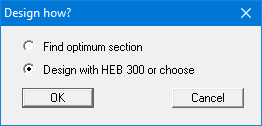
For the example, select the "Design with HEB 300 or choose" check box and confirm by pressing 'OK'. The dialog box with the settings for design to EC 3 then opens:
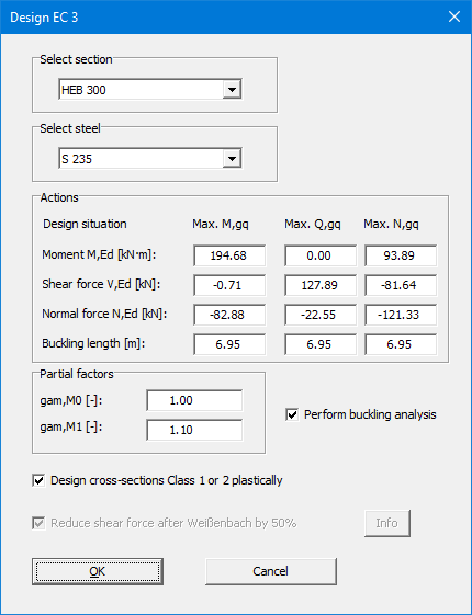
Enter the values in the dialog box and confirm with "OK". When the following message box opens, confirm.
The design values for the soldier pile are then displayed in a message box. The data can be copied to a report via the Windows clipboard, for example, by pressing the "To clipboard" button.
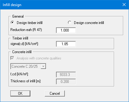
After leaving the result box, the infill walling design dialog box opens:
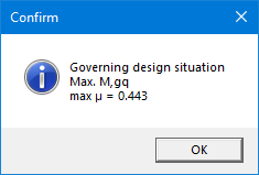
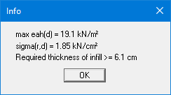
The result is displayed in a message box after pressing "OK":
The check boxes activated by default in menu item "Editor 1/Verifications/Partial factors" are "Perform 'Vertical capacity' analysis (EAU, EAP and EAB)" and "Perform 'Sum V' analysis". The following dialog box therefore opens once the infill walling has been designed:
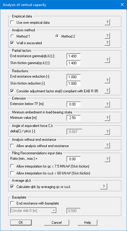
A minimum embedment in load-bearing ground is not demanded in the EAU and EAB. The specified value of 2.50 m is guided by the Recommendations on Piling (EA-Pfähle). You can therefore set the value for the minimum embedment depth to 0.0 m.
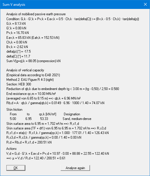
After clicking the "Analyse again" button it is possible to make changes to the above dialog box to analyse the vertical capacity and have the analysis performed again.
Leaving the box with "OK", the earth pressure distribution, the moment, shear force profile and normal force profiles, as well as the bending line, will be displayed on the screen. The analysis and design of the retaining wall are complete.
Step 9: Evaluate and visualise the results
Four legends appear on the screen, containing the soil properties, the main elements on which the analysis is based, and the main design results. The fourth legend contains a diagram of the retaining wall (see below).

Figure 2 Retaining wall diagram
The graphics can be printed on the selected printer ("File/Print and export" menu item). You can also print off a detailed protocol ("File/Print output table" menu item). The zoom function (see "Graphics preferences/Zoom info" menu item) allows you to magnify selected areas of the graphic. Double-clicking in the graphics at a particular point will cause a box to appear containing the corresponding state variables.
Other forms of evaluation are possible from the "Evaluation" menu, which will display the selected type of earth pressure redistribution, the design parameters, the maximum values and the anchor forces. The menu item "Evaluation/Deep-seated stability summary" is of particular interest:
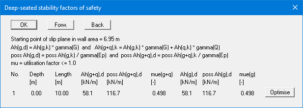
A utilisation factor of 0.498 was determined for the example. Clicking "Optimise" will adjust the anchor length accordingly. The anchor length necessary for a utilisation factor of 0.995 will be displayed after a few seconds. Changing anchor length radically alters the structural system, since the total axial stiffness of the anchor is increased. Thus, following optimisation, a corresponding warning box appears. In practice, the effect of the changes on cross-section through optimisation is usually small and can be neglected. However, if you are unsure, it is better to reanalyse.
If you wish to add explanatory text or graphic elements, you can do so using the "Mini-CAD" module. You can save your work in a file by clicking "File/Save as".