
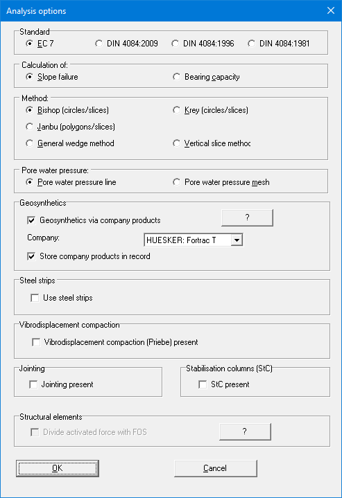
You will see the following dialog box:
-
"Standard" group box
You select the standard to which the slope stability analysis is to be performed. -
"Calculation of:" group box
You can then specify whether slope stability (default) or bearing capacity is to be analysed. Additional information on a strip footing is required for bearing capacity analysis (see Section 10.2.16). The safety is then acquired from a comparison of the failure load Vb and the working strip footing load Vwork. :
![]()
For an analysis of bearing capacity the program varies the load Vb until the slope stability FOS ![]()
-
"Method:" group box
Select the method to be adopted. The menu bar changes according to the choice made here, showing either "Centre-points" or "Slip body". -
"Pore water pressure:" group box
Generally, pore water pressures in slopes are defined using a pore water pressure line. Geotechnical applications (including GGU-STABILITY) compute the pore water pressure at the slice toe from the vertical distance between the slice toe and the pore water pressure line lying above it. Implicit in this procedure is the assumption that the slope is only percolated horizontally. This assumption is sufficiently precise for many slopes.
However, this assumption is no longer justified for complex flow conditions (e.g. embankment with exterior seal). Consideration of artesian conditions is also only helpful in a few special cases. Complex flow conditions can therefore only be correctly taken into consideration if the pore water pressure is defined at every point of the slope.
With GGU-STABILITY it is possible to define these pressures by means of a pore water pressure mesh (triangular mesh), which must cover the whole area of the slope under investigation. The appropriate mode is activated using the "Pore water pressure mesh" option button. The "Pwp mesh" menu, with a total of 15 menu items, is available for defining the triangular mesh. -
"Geosythetics" group box
When using geosynthetics it is easiest to adopt company products. The "Geosythetics via company products"check box is activated when the program starts and the preferred geosynthetics manufacturer can be selected in the options menu.
When subsequently defining the geosynthetics you can select between the products of the manufacturer defined here and their product range (see menu item "Nail wall/Enter nails manually" or "Nail wall/Generate" and the "Geosynthetics" button in "Editor 1/Enter system parameters").
Activation of the '"Store company products in record" check box in the above dialog box is the recommended setting. Otherwise, if the file is opened on a computer that does not have the ".ggu-geo" files installed, the originally selected products are deleted. The product lists of the various geosynthetics manufacturers can be selected and edited in the menu item "Editor 1/Geosynthetics table values". -
"Steel strips" group box
Activate this check box if you would like to use steel strips for slope stabilisation. In the menu item "Editor 1/Enter system parameters" you will then be offered the "Steel strips" button instead of the "Geosynthetics" button. -
"Vibrodisplacement compaction" group box
Activate vibrodisplacement compaction adoption after Priebe (Heinz J. Priebe, Die Bemessung von Rüttelstopfverdichtung, Ground Engineering, December 1995) using the "Vibrodisplacement compaction (Priebe) present" check box. It is then possible to enter the appropriate parameters for the improved soil stratum (see menu item "Editor 1/Enter system parameters" button "Soil properties") -
"Jointing" group box
Using the "Jointing present" check box, you activate the adoption of soils with jointing, which can subsequently be defined in the menu item "Editor 1/Enter system parameters" button "Soil properties". -
"Stabilisation columns (StC)" group box
Activate analysis using stabilisation columns after Neidhart/Gömmel using the "StC present" check box (Gömmel, R., Neidhart, T. (2016): Zum Ansatz von Stabilisierungssäulen beim Nachweis der Gesamtstandsicherheit. 10. Kolloquium Bauen in Boden und Fels, S. 399–409, Technische Akademie Esslingen e.V. (Hrsg.), ISBN 978-3-943563-21-4).
The stabilisation columns can then be defined in the menu item "Editor 1/Enter system parameters" using the "StC" button. -
"Structural elements" group box
The literature provides several examples which divide the force of the tension member of soil dowels (e.g. DIN 4084, Example 1), geosynthetics and soil nails by the current FOS and then consider this value in the numerator of the relationships after Bishop or Janbu. Normally the check box "Divide activated force with FOS" can be deactivated. The forces from structural elements are then incorporated into the equation without reductions.
If you have selected the partial safety factor concept to DIN 4084:1996 or DIN 4084:2009 and then exit the dialog box using "OK", you first get the dialog box for defining the partial safety factors (see menu item "Editor 1/Partial factors, ...").