
If cohesive layers are loaded faster than they can release their pore water, excess pore water pressures result, which are only gradually dissipated. This process is known as consolidation. For a one-dimensional case a closed solution exists (see e.g. Das; Advanced Soil Mechanics; McGraw Hill). The following input values are required:
-

-
Es = constrained modulus of layer
-
k = permeability of layer
-
d = thickness of layer
-
t = time at which the excess pore water pressure is to be determined.
Further to this, the drainage conditions of the layer are to be considered:
-
draining to the top and bottom
-
draining to the top only
-
draining to the bottom only
The program allows input of these values via so-called consolidation layers.
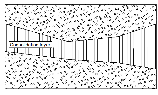
Consolidation layers are defined by two boundary polygons. Each polygon point must be assigned a pore water pressure. In Figure 13, a consolidation layer is shown which can drain to the top and the bottom. Due to the non-horizontal position, a two-dimensional consolidation will actually take place. The program calculates with one-dimensional consolidation in the vertical direction with sufficient precision and generally on the safe side. If a slice foot is within the layer, the layer thickness is determined from the two polygons. Together with the vertical position within the layer and the other decisive quantities, the program determines the excess pore water pressure at the user-defined time. If you calculate with consolidation layers, it may be necessary to carry out several calculations for the same system, using different times.
Besides classical consolidation theory, the program also commands cases in which the consolidation is accelerated by vertical drains (e.g. sand drains). The principles are explained in Das; Advanced Soil Mechanics; McGraw Hill.
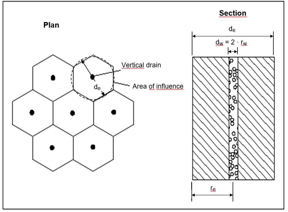
The honeycomb structure around a drain can be converted to an equivalent circle, so that an axis-symmetrical consolidation calculation can be carried out for each drain. In this case, according to theory, dissipation of excess pore water pressure only takes place horizontal to the drains (axis-symmetrical), so the drainage conditions at the top and base of the layer need not be given. Instead, the drained distance (de) to one another and the radius (rw) of the drains must be given. In consolidation layers with vertical drains the excess pore water pressure at any time is constant across the layer depth. The excess pore water pressure is, however, variable as a function of the distance re from the axis of the vertical drain. The program determines the average pore water pressure distribution.
The calculated pore water pressure distribution can be made visible very nicely, if you activate, from the menu item "Safety/Utilisation factors/Preferences", the switch
However, this does not work for calculations according to "General wedge method" or the "Vertical slice method". In these cases, you can take the values from the data protocol in "Safety factors (Utilisation factors)/Display results".