
After completing the centre-point definition, a search grid must be specified. Select the "Define search grid" item from the "Centre-points" menu. The following dialog box appears:
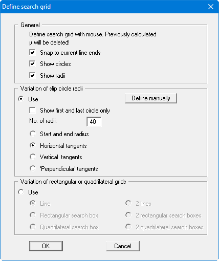
In the "General" group box you can alter presentation preferences. In the other two input group boxes you can vary the search grid by means of slip circle radii or rectangular and quadrilateral search boxes. Activate the "Use" button in the required variation group box. In addition to the following discussion, further examples for defining the search grid can be found in the "Centre-points/Define search grid" menu item.
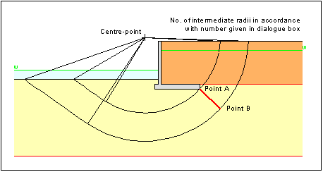
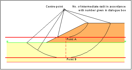
For "Variation of slip circle radii" the search grid is characterised by two points A and B, which must be clicked by the mouse. There are four different types of definition:
-
"Start and end radius"
All radii pass through point A and point B. Subdivisions between these two are in accordance with the user-defined number of radii.
-
"Horizontal tangents"
All radii touch a horizontal tangent, which is defined by the points A and B. Subdivisions between these two are in accordance with the user-specified number of radii.
If the location of the governing search grid cannot be unequivocally identified from the system, it makes sense to define Top of slope and Base of system as points A and B.
-
"Vertical tangents"
All radii touch a vertical tangent, which is defined by the points A and B. Subdivisions between these two are in accordance with the user-specified number of radii. This method is of only minor importance. -
"Perpendicular tangents"
All radii touch a tangent, the rise of which is specified as being normal to a line connecting points A and B. Subdivisions between these two are in accordance with the user-specified number of radii. This method is of only minor importance.
After confirming with "OK", click on two points (A and B) within the slope. The boundary radii will then be displayed. If you are not satisfied with your choice, you can then immediately click on two new points.
Note:
For bearing capacity analysis with a footing within the slope, definition of a search grid is not necessary. The search grid will be set automatically. The left or right footing edge will be defined as search radius depending on slip body movement.
For "Variation of rectangular or quadrilateral grids" you also have the option of selecting between a number of methods. After selecting the method to be adopted and entering the subdivisions in a dialog box, the selected element (line, rectangular search box, etc.) is displayed on the screen. In this manner you have an example for application of the individual procedures and, in analogy, can subsequently try out your own definitions.
For example, select "Rectangular search box". The number and spacing of the slip circles is varied according to the defined array subdivision and the size of the search box subsequently represented on the screen. The search grid is restricted to the array used in the line or search box. To facilitate better understanding, try a gradual increase in subdivisions in x and y directions from 1 upwards.
If, in the above dialog box, you activate the "Snap to current line ends" check box, a small square is displayed around the mouse points. The mouse pointer then locks on to the end points of surface lines, etc., that lie within this square when clicked.
If, in the dialog box above, the "Show circles" and "Show radii" check boxes are deactivated, the limit radii will not be displayed when defining the search area. This generally only makes sense for very slow computers. This is similar to the "Show first and last circle only" check box, which allows only the limit radii of the first and last centre-points to be displayed. The configuration of these check boxes does not influence subsequent analysis evaluation.