
DIN 4084 (January 2009 edition) differs significantly from the previous DIN 4084 published in 1981.
DIN 4084-100 (referred to below as DIN 4084:1996!), which also included the new partial safety factor concept, was published as a draft in 1996. New analysis methods (general wedge mechanism and vertical slice methods) were described using examples in an unpublished supplement to this standard. These methods were implemented in the GGU-STABILITY program in 1996. These methods are not standard-dependent and therefore also apply to the global safety factor concept.
DIN 4084:1996 also included completely new designations for determination of stability using Bishop and Janbu methods (circular and non-circular slip surfaces). These equations were not initially implemented and were put on hold until the official introduction of the DIN 4084:1996. In GGU-STABILITY, therefore, the designation "DIN 4084:1996" means that stability is analysed using the equations published in DIN 4084 from 1981, but with the definitions of the partial safety concept. Analysis uses the design variables φd and cd.
tan φd = tan φk / γφ
cd = ck / γc
φk and ck = characteristic shear strength values
φd and cd = shear strength design values
In addition, partial factors must be applied to live loads (e.g. 1.3 in Load Case 1). Stability is then analysed using the modified values. This gives the safety factor η in accordance with the global safety factor concept, but relative to the design values. The reciprocal of this "global safety factor ηd" gives the utilisation factor µ in accordance with the partial safety factor concept:
µ = 1 / ηd
It was not until January 2009 that this concept was made mandatory. The new DIN 4084:2009 was primarily based on the relationships defined in DIN 4084:1996. However, it also includes considerable modifications. All new relationships are implemented in their entirety in the current version of the GGU-STABILITY program.
Comparative analyses using existing examples found in the literature and existing standards indicate very minor deviations between the old and the new standards.
Beside the new equations for Bishop and Janbu, one principal difference to the old standard is found in the definition of the passive tension member. It states that the force from a tension member may only be adopted if the boundary conditions shown in Figure 11 are adhered to.
Excerpt from DIN 4084:2009:
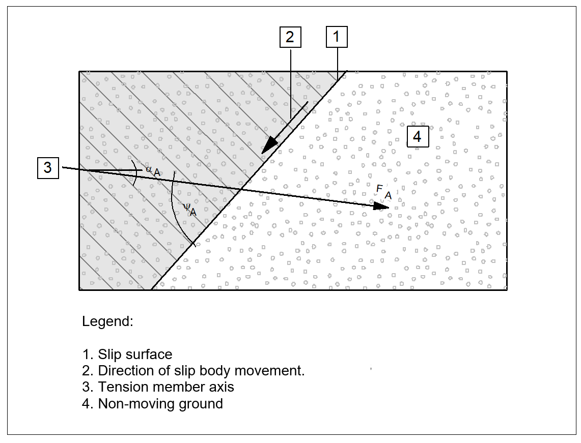
"A tension member is regarded as self-tensioning if the slip body in which the head of the tension member is located move approximately as a rigid body on a slip surface and the angle ψA between the tension member axis and the most unfavourable slip surface (Figure 11) achieves the following maximum values:
-
for loose, cohesionless soils or soft, cohesive soils: ψA = 75°;
-
for firm, cohesive soils: ψA = 80°;
-
for medium-dense, cohesionless soils and stiff, cohesive soils: ψA = 85°;
-
for dense, cohesionless soils: ψA = 90°.
The tensile force of passive tension members must be determined to DIN 4084 7.2.1.
7.2.1 For analyses using this standard, the design values of the resisting forces exercised by tension members, dowels, piles and struts are acquired from the characteristic values for either the pull-out resistances, dowel resistances or penetration resistances, by dividing by the partial factors to DIN 1054 or the design values for allowable stresses according to the corresponding construction standards. The respectively smaller value is adopted. The acceptable forces on dead men or anchor slabs must be determined using the design values for ground resistances.
NOTE: Non-passive tension members, which are not prestressed, have no effect.
Where a wall is supported by tension members with angles ψA greater than the boundary values given in 7.2.3.4, a tension member may be taken into consideration at any angle if the wall can only rotate around a vertically and horizontally immoveable point at the base of the wall because of the support situation around the toe area. In this case the force necessary to accept the design values for earth and water pressures must be adopted as the tensile force for analysing sufficient global stability."
The settings described can be modified in the lower group box of the "Editor 1/Partial factors, …" dialog box and apply to all types of tension members definable in GGU-STABILITY.
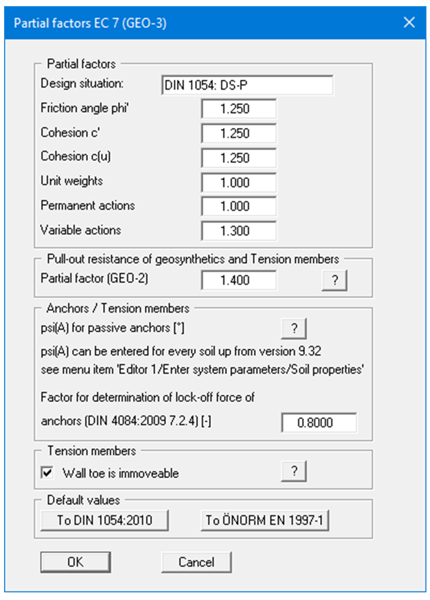
If the "Wall toe is immoveable" check box is activated in GGU-STABILITY, the information to DIN 4084:2009 in Figure 11 is ignored.
Implementation of the new standard was carried out with great care over a period of approx. two months. Competent examination of the implementation was not possible due to the lack of eligible examples available. The examples relating to the new DIN 4084:2009 are to be published by the standardisation committee in 2013.
Seven examples are available for DIN 4084:1996; however, they were never published. These examples are provided as GGU-STABILITY files with the program.
"DIN 4084-100-1996 Bsp 1.boe"
to
"DIN 4084-100-1996 Bsp 7.boe"
The partial factors defined at that time envisaged different values for friction angle and cohesion:
-
E.g. for Load Case 1
γφ = 1.25 and
γc = 1.60
Accordingly, the examples also include these different partial factors. The partial factors for friction angle and cohesion are the same in the new DIN 4084:2009.
-
E.g. for Load Case 1
γφ = 1.25 and
γc = 1.25
The utilisation factors µ computed in the examples therefore do not correspond to those in the current version of the standard.
A comparison of the results in the examples (DIN 4084:1996) with those given by GGU-STABILITY displays an excellent correlation.