
The coordinates of the pore water pressure line are entered as a polygon course. The x-values of the polygon course must increase from left to right. From the vertical distance between the slice foot and the point on the pore water pressure line above this, the program calculates the valid pore water pressure (u) for the slice. If the pore water pressure line lies below the slice foot, the pore water pressure will be set to zero.
The pore water pressure line must cover the whole of the area to be investigated in the calculations. If no pore water pressures are present you can simply define a pore water pressure line which consists of two points, and which runs below any possible y-values of the slice feet.
If a phreatic line is present within the slope, this line is generally a pore water pressure line.
The example system has 5 pore water pressure points. First, select the "Pore water press." button in the central dialog box and then, alter the number of pore water pressure points to 5 using the "x pwp point(s) to edit" button. Enter the values shown in the following dialog box:
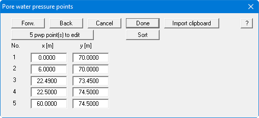
For deleting and pasting of pore water pressure points see the note in "Surface points".
The pore water pressure points can also be imported via the Windows clipboard. For example, if the x/y coordinates of the pore water pressure points are available in an Excel table, it is possible to copy the two columns containing the data into the Windows clipboard ("Edit/Copy") and then to paste them into the dialog box shown above by pressing "Import clipboard".