
Using this menu item, you make basic settings for the nail wall. The "Calculate wall" check box must be activated for this. First select the elements making up the wall.
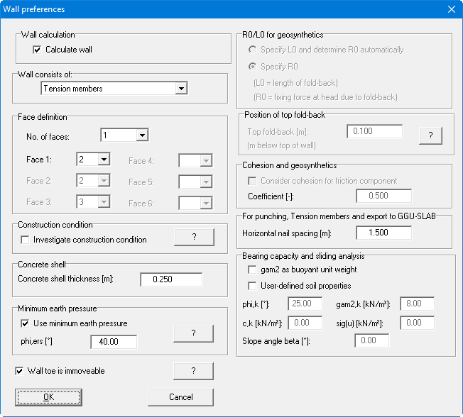
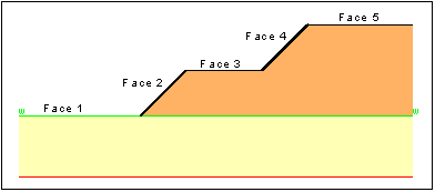
The faces are sections of the defined terrain polygon course. They are continuously numbered from left to right. In the GGU-STABILITY program it is possible to define up to a maximum of six nailed slope faces. To do this, enter the number of nailed slope faces and assign these faces the corresponding face numbers (see Figure 33). The thus defined slope faces are highlighted in the graphics with a line wall. The thickness of the 'wall' can be altered using the menu item "Nail wall/Graphics" .
Corresponding to the selected element various input areas will be activated. Explanations can be found by clicking on the "?" buttons.
The force R0 designates an anchorage at the head of the geosynthetics, e.g. in a gabion wall. If you have selected "Geosynthetics" as nailing element and "Specify L0 and determine R0 automatically" you enter the fold-over length L0 when generating the geosynthetics. The program will then automatically calculate the force R0 from the fold-over length.
The "Concrete shell thickness" and the "Horizontal nail centres" are important for punching verification, tension members and for data export to GGU-SLAB.
Further information on the "Investigate construction condition" check box can be read by clicking the "?" button.
If the "gam2 as buoyant unit weight" check box is activated, this is taken into consideration accordingly when verifying bearing capacity (see "Theoretical principles"). If the soil properties in the ground deviate from the automatically determined mean values, activate the "User-defined soil properties" check box. Then, it is also possible to employ user-defined soil properties in the following input boxes.