
To emphasise the universal usefulness of this structural element the original "Injection pile" designation was changed to "Tension member". You can modify designation at will (e.g. to "Soil nails") in the "Editor 1/Tension member designations" menu item to make program output more legible to third parties.
When defining tension members, the acceptable friction forces are determined using the shaft friction qs,k defined for each soil. The following example can be found as "Example manual tension member.boe" file in the program's example folder.
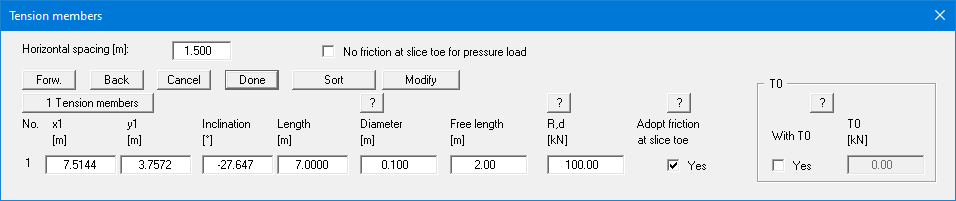
The following data are required for tension members:
-
x1, y1 = tension member head coordinates
-
Inclination = tension member inclination
-
Length = tension member length
-
Diameter = diameter D of tension member
-
Free length = length from tension member head excluding grouted section
-
R,d = design value of material resistance
-
T0 = anchoring force at the head
If the "Adopt friction at slice toe" check box is activated, the friction generated by the friction force in the corresponding slice is adopted.
The following tension member is given by the input in the above dialog box:
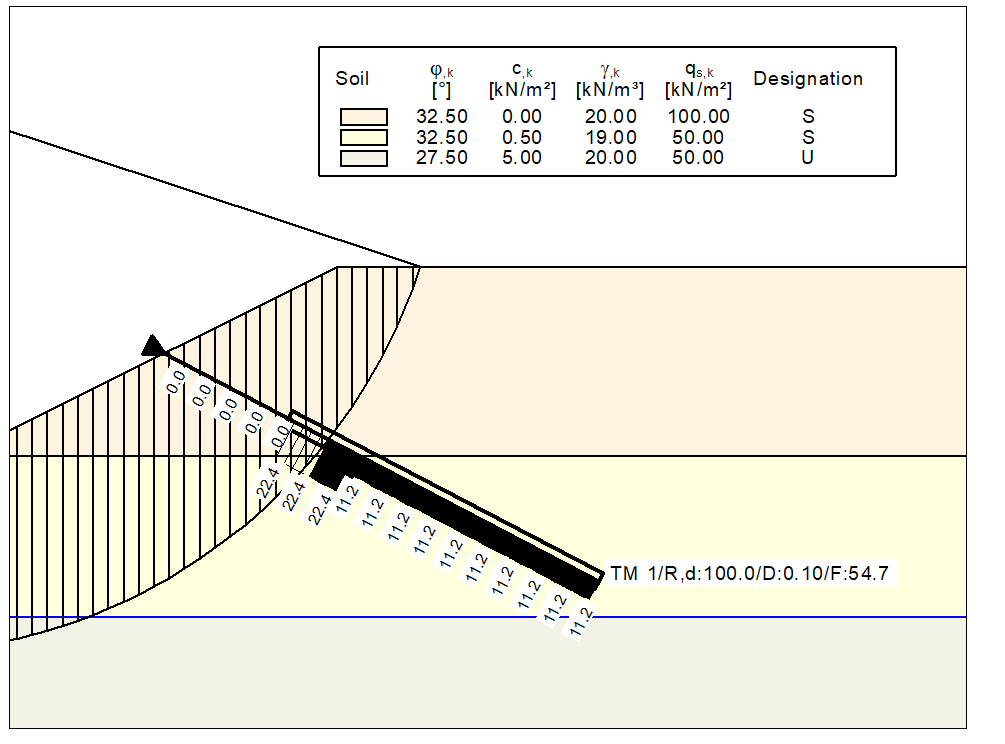
A characteristic shaft friction qs,k of 100.0 kN/m² has been entered for Soil 1 and 50.0 kN/m² for Soil 2. The program computes the bonding stress τ using:
τ = qs,k · π · D / γN
-
D = diameter = 0.2 m
-
γN = 1.40 = pull-out resistance partial factor
(entered in "Editor 1/Partial factors, …") -
τ (Soil 1) = 22.4 kN / m²
-
τ (Soil 2) = 11.2 kN / m²
This allows the pull-out force to be computed by integration, see the blackened region in the above graphics. If the integral value becomes greater than R,d integration is aborted.