
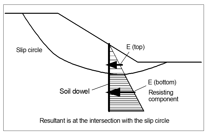
The action of soil dowels is shown in the following figure:
For input, select the "Dowels" button and enter the number of soil dowels in accordance with the previous description. Then, the coordinates of the soil dowel and the values of the earth pressures e1,d and e2,d to be transmitted by the soil dowel must be entered. If the soil dowel consists of, e.g., a 0.75 m diameter pile which can activate a lateral earth pressure e,d of 25 kN/m² constantly along its length, and has a pile spacing perpendicular to the observation plane of 2.1 m, the earth pressure force to be entered is
25 · 0,75/2,1 = 8,9 kN/m² · m/m = 8,9 kN/m/m
Soil dowels will naturally only then be considered when the dowel intersects the slip surface.
The earth pressure force component which lies outside of the slip body is determined, and added to the lever arm of the intersection of the soil dowel with the slip circle centre-point. For polygonal slip surfaces, only the horizontal component of the earth pressure force is considered. If the start and end points lie outside of the slip body and two intersections with the slip body are present, the soil dowel force will not be considered. After calculations, that part of the soil dowel which was taken into account will be colour-filled, so that simple checking is possible.
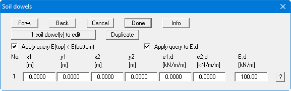
If you activate the "Apply query E(top) < E(bottom)" check box the earth pressures ranges are investigated (see above Figure 18). The smaller of the earth pressures is adopted for the analysis.
e1,d and e2,d are design values from the new standard and describe the magnitude of the axial forces in kN/m/m. E,d is the design force that can be accepted by the soil dowel. If the "Apply query to E,d" check box is activated, the computed dowel force cannot become larger than E,d (see also "Info" button).
Example 1 of Supplement 2 of DIN 4084 contains an H pile system, which can be considered as soil dowels.