GGU-CANTILEVER: Reinforced concrete design
Reinforced concrete is designed to EC 2 or, alternatively, to DIN 1045 (old) depending on the selected safety factor concept. Reinforcement is calculated for all wall element sections (see “Theoretical principles: Structural system”). The output is the section with the largest reinforcement.
The stem area above the footing is designed using the wall internal forces (see “Theoretical principles: Cantilever wall-Determination of wall loads for reinforced concrete design“).
The internal forces M and Q at the stem base/toe and heel intersections are calculated from the soil pressure and the loads on the spur. The model concept is a cantilever fixed at the intersection with the wall. The normal force N results from the passive earth pressure.
The following vertical loads are applied to the heel (earth-side spur):
- Soil pressure below the spur (upwards)
- Self-weight of the spur
- Soil above the spur up to the equivalent wall, including any slope wedge
- Vertical component of the earth pressure on the equivalent wall, applied at the end of the spur as a downward load (since version 6.3)
- Uniform surcharge, block loads and loads with one-sided or two-sided limits in the area above the spur
- Base water pressure (relieving)
The toe (air-side spur) is loaded by the soil pressure, the self-weight of the spur, the soil above the spur, the base water pressure and the vertical component of the passive earth pressure.
The horizontal component of the earth pressure on the equivalent wall is not included in the spur moment. The spur moment is determined independently of the wall moment, i.e. not from the equilibrium at the wall intersection (wall moment and moment of the other spur). It can therefore differ considerably from the wall moment and may also be larger, for example with a slope behind the wall that produces a large vertical component of the earth pressure.
If one spur is no more than 0.10 m wide, the larger absolute value of the cantilever moment and the wall moment at the intersection is used for the other spur.
Soil pressure and loads on the spur are always applied with the full live load. The "Investigate "No traffic on spur" load case" check box (see "New" menu item) only affects the stability analyses, not the reinforced concrete design (since version 6.2). For the design values, the permanent components including the soil pressure are multiplied by the partial safety factor for permanent actions and the live load components by the partial safety factor for variable actions.
If the base joint gapes over more than half the footing width, no internal forces are determined for the spurs.
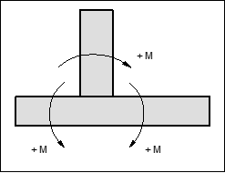
The following sign rule applies to the spur and wall moments with reinforcement: