
"New" menu item
You can enter a new system using this menu item. You will see the following dialog box:
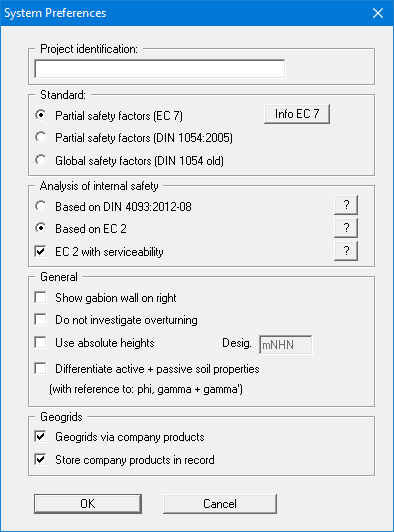
You can enter a dataset description ("Project identification"). of the problem going to process, which will then be used in the "General legend" (see section 8.7.8).
In the next group box, the radio buttons are used to specify which safety concept to use for analysis and design.
By default, analysis of internal stability is based on EC 2 as an analysis of the unreinforced concrete (see section 7.25.2). We recommend analysing the serviceability limit state, including when using EC 2 (see section 7.25.3.2). Alternatively, you can analyse internal stability based on DIN 4093:2012-08 (see section 7.25.3). This then includes the serviceability analysis.
Additionally, gabion wall visualisation to the right can be activated. DIN 1054:2005 states that an overturning analysis may be dispensed with for Load Case 3 if sufficient bearing capacity has been demonstrated. This rule is no longer included in Eurocode 7; it is therefore always necessary to perform an overturning analysis. In justified exceptional cases, however, the analysis may be turned off using the "Do not investigate overturning" check box.
If you select the "Use absolute heights" check box, you can enter all depths and heights in m AD (heights are positive upwards). If you leave this box unselected, the top of the wall is assumed at 0.0 (height/depth) and all input of layer depths etc. is positive downwards. If, however, you want to work with absolute heights, enter the appropriate depths correspondingly altered. Thanks to WYSIWYG there is no danger of using incorrect data, since all input is immediately visible on the screen.
If your system uses differing soil properties on the active and the passive sides, activate the "Differentiate active + passive soil properties" check box in the above dialog box. You will then be presented with different input columns for entering the active and passive friction angle and unit weight soil properties in the "Editor 1/Soils" menu item (section 8.2.8). For better visualisation you can define the soil colours on the active and the passive sides differently using the Soil properties legend (see section 8.7.7).
If the "Geogrids via company products" check box is activated, it is possible to select the products of various geogrids manufacturers from a list stored in the program when entering geogrids (see menu item "Reinforced soil system/Enter geogrids manually" or "Reinforced soil system/Generate geogrids"). We also recommend activating the "Store company products in record" check box. Otherwise, if the file is opened on a computer that does not have the ".ggu-geo" files installed, the originally selected products are deleted. The product lists of the various geogrids manufacturers can be selected in the menu item "Editor 1/Geogrids table values" (see section 8.4.10).
If the dialog box is changed from Global safety factor concept to Partial safety factor concept, an additional dialog box for specifying the partial factors opens after your input has been confirmed. By pressing the 'Default values' button the partial factors for the various load cases given in DIN 1054:2005 and EC 7 can be adopted. The partial factors entered can be edited at any time using the 'Editor 1/Verifications/Partial factors' menu item (see section 8.2.15).
"Load" menu item
You can load a file with system data, which was created and saved at a previous sitting, and then edit the system.
"Save" menu item
You can save data entered or edited during program use to a file, in order to have them available at a later date, or to archive them. The data is saved without prompting with the name of the current file. Loading again later creates the same presentation as was present at the time of saving.
"Save as" menu item
You can save data entered during program use to an existing file or to a new file, i.e. using a new file name. For reasons of clarity, it makes sense to use ".gab" as file suffix, as this is the suffix used in the file requester box for the menu item "File/Load". If you choose not to enter an extension when saving, ".gab" will be used automatically.
"Print output table" menu item
Selecting the output format
You can have a table printed containing the current analysis results. The results can be sent to the printer or to a file (e.g. for further editing in a word processor). The output contains all information on the current state of analysis, including the system data.
You have the option of designing and printing the output table as an annex to your report within the GGU-GABION application. To do this, select "Output as graphics" from the following options.
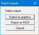
If you prefer to easily print or process the data in a different application, you have the possibility of sending them directly to the printer or to save them to a file using the "Output as ASCII" command button.
"Output as graphics" button
If you selected the "Output as graphics" button in the previous dialog box a further dialog box, in which you can define further preferences for result presentation.
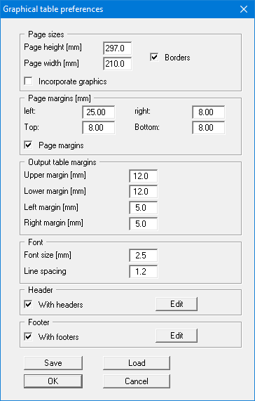
In the various group boxes of the dialog box, you can define preferences for the table output and layout. By activating the "Incorporate graphics" button, a sketch of the system is integrated in the output table. If you need to add a header or footer (e.g. for page numbering), activate the appropriate check boxes "With headers" and/or "With footers" and click on the "Edit" button. You can then edit as required in a further dialog box. You can save your settings for the graphical output table presentation in a "Protokoll.pin_ggu" file at the program level so that they are loaded when the program starts. Using the "Load" button, the output table settings can also be subsequently loaded into an existing file, including that of another GGU program.
Annex 4.1 Output table
Page 1 of 3
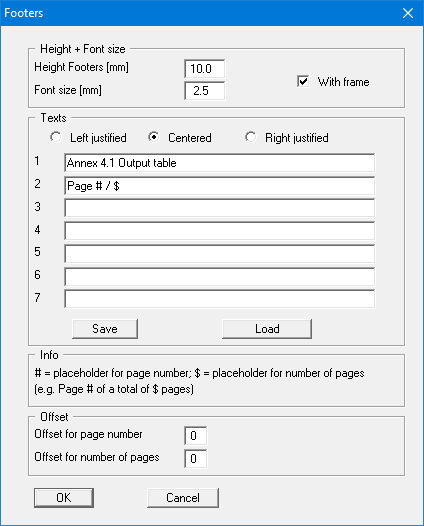
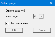
Automatic pagination can also be employed here if you work with the placeholders as described. After closing the dialog box using "OK" the output table is shown page by page on the screen. To navigate between the pages, use the arrow tools in the toolbar. If you need to jump to a given page or back to the graphical visualisation, click on the tool. You will then see the following box:
"Output as ASCII" button
You can have your analysis data sent to the printer, without further work on the layout, or save it to a file for further processing using a different program, e.g. a word processing application.
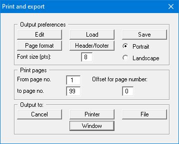
In the dialog box you can define output preferences.
"Output preferences" group box
Using the "Edit" button the current output preferences can be changed or a different printer selected. Using the "Save" button, all preferences from this dialog box can be saved to a file in order to have them available for a later session. If you select "GGU-GABION.drk" as file name and save the file in the program folder (default), the file will be automatically loaded the next time you start the program.
Using the "Page format" button you can define, amongst other things, the size of the left margin and the number of lines per page. The "Header/footer" button allows you to enter a header and footer text for each page. If the "#" symbol appears within the text, the current page number will be entered during printing (e.g. "Page #"). The text size is given in "Pts". You can also change between "Portrait" and "Landscape" formats.
"Print pages" group box
If you do not wish pagination to begin with "1" you can add an offset number to the check box. This offset will be added to the current page number. The output range is defined using "From page no." "to page no.".
"Output to:" group box
Start output by clicking on "Printer" or "File". The file name can then be selected from or entered into the box. If you select the "Window" button the results are sent to a separate window. Further text editing options are available in this window, as well as loading, saving and printing.
"Export" menu item
The general stability can be simply verified by exporting the data from GGU-GABION to GGU-STABILITY (GGU slope stability application). After clicking this menu item an appropriate file (".boe") can be generated with the required GGU-STABILITY version status.
"Output preferences" menu item
You can edit output preferences (e.g. swap between portrait and landscape) or change the printer in accordance with WINDOWS conventions.
"Print and export" menu item
You can select your output format in a dialog box. You have the following options:
"Printer"
allows graphic output of the current screen contents (graphical representation) to the WINDOWS standard printer or to any other printer selected using the menu item "File/Output preferences". But you may also select a different printer in the following dialog box by pressing the "Output prefs./change printer" button.
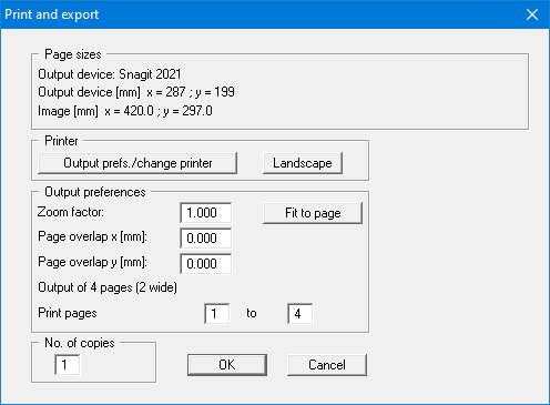
In the upper group box, the maximum dimensions which the printer can accept are given. Below this, the dimensions of the image to be printed are given. If the image is larger than the output format of the printer, the image will be printed to several pages (in the above example, 4). In order to facilitate better re-connection of the images, the possibility of entering an overlap for each page, in x and y direction, is given. Alternatively, you also have the possibility of selecting a smaller zoom factor, ensuring output to one page ("Fit to page" button). Following this, you can enlarge to the original format on a copying machine, to ensure true scaling. Furthermore, you may enter the number of copies to be printed.
If you have activated the tabular representation on the screen, you will see a different dialog box for output by means of the "File/Print and export" menu item button "Printer".
Here, you can select the table pages to be printed. In order to achieve output with a zoom factor of 1 (button "Fit in automatically" is deactivated), you must adjust the page format to suit the size format of the output device. To do this, use the dialog box in "File/Print output table" button "Output as graphics".
"DXF file"
allows output of the graphics to a DXF file. DXF is a common file format for transferring graphics between a variety of applications.
"GGU-CAD file"
allows output of the graphics to a file, in order to enable further processing with the
GGU-CAD program. Compared to output as a DXF file this has the advantage that no
loss of colour quality occurs during export.
"Clipboard"
The graphics are copied to the WINDOWS clipboard. From there, they can be imported into other WINDOWS programs for further processing, e.g. into a word processor. In order to import into any other WINDOWS program, you must generally use the "Edit/Paste" function of the respective application.
"Metafile"
allows output of the graphics to a file in order to be further processed with third party software. Output is in the standardised EMF format (Enhanced Metafile format). Use of the Metafile format guarantees the best possible quality when transferring graphics.
If you select the "Copy/print area" tool from the toolbar, you can copy parts of the graphics to the clipboard or save them to an EMF file. Alternatively you can send the marked area directly to your printer (see "Tips and tricks", section 9.4).
Using the "Mini-CAD" program module you can also import EMF files generated using other GGU applications into your graphics (see section 8.7.5).
"Mini-CAD"
allows export of the graphics to a file in order to enable importing to different GGU applications with the Mini-CAD module.
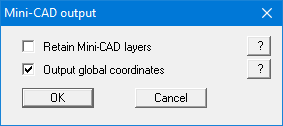
If the "Retain Mini-CAD layers" check box is activated, the layer allocations for any existing Mini-CAD elements are saved. Otherwise, all Mini-CAD elements are saved on Layer 1 and are also inserted into Layer 1 in other GGU programs via the "Load" function in the Mini-CAD pop-up menu.
By activating the "Output global coordinates" check box, the present graphics are saved in the system coordinates [m]. Otherwise they are saved in the page coordinates [mm]. If you import the Mini-CAD file saved using "Global coordinates" into a different GGU program, the coordinates are also transferred. If a system is transferred from GGU-STABILITY to GGU-2D-SSFLOW, for example, the system coordinates and scale are corrected compliant with the transferred global coordinates, after importing the file and pressing the function key [F9] (menu item "Page size + margins/Auto-resize").
"GGUMiniCAD"
allows export of the graphics to a file in order to enable processing in the GGUMiniCAD program.
"Cancel"
Printing is cancelled.
"Batch print" menu item
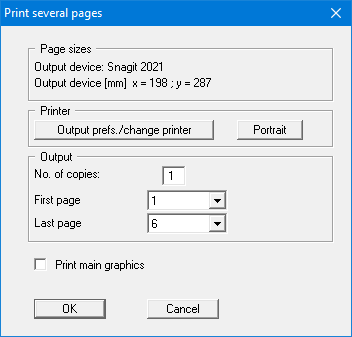
If you would like to print several annexes at once, select this menu item. You will see the following dialog box:
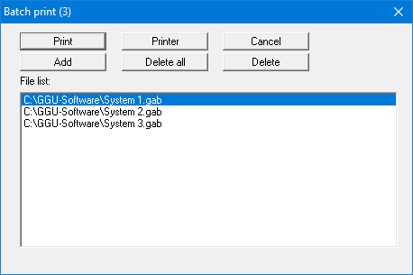
Create a list of files for printing using "Add" and selecting the desired files. The number of files is displayed in the dialog box header. Using "Delete" you can mark and delete selected individual files from the list. After selecting the "Delete all" button, you can compile a new list. Selection of the desired printer and output preferences is achieved by pressing the "Printer" button.
You then start printing by using the "Print" button. In the dialog box which then appears you can select further preferences for printer output such as, e.g., the number of copies. These preferences will be applied to all files in the list.
"Exit" menu item
After a confirmation prompt, you can quit the program.
"1, 2, 3, 4" menu items
The "1, 2, 3, 4" menu items show the last four files worked on. By selecting one of these menu items the listed file will be loaded. If you have saved files in any other folder than the program folder, you can save yourself the occasionally onerous rummaging through various sub-folders.